 ®

Technical guide
How to Read the Thrust, Lubrication and Cooling Parameters of a ZLYJ Extruder Gearbox
Author: CHINFAR Technical Team · Reviewer: Tinyuen (CHINFAR) · Updated: 2026-11-04
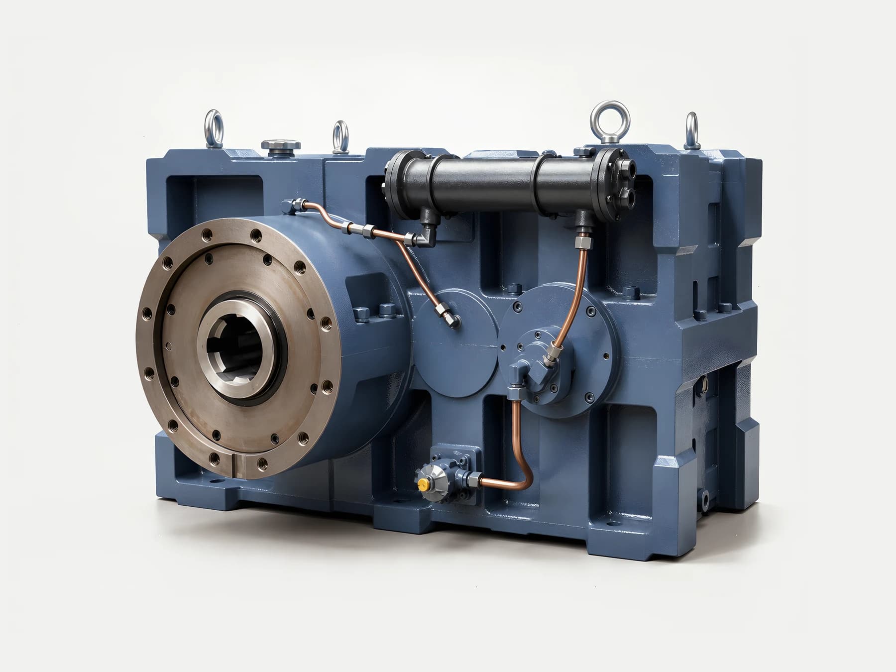
Reading a ZLYJ parameter table is hard for one reason: the fields are tied to each other, not hard to memorise. Six fields matter — thrust load, oil charge, oil temperature, cooling method, life and lubrication type — and these are not independent ratings. Raise the thrust load and the bearing arrangement and housing must follow. Raise the oil temperature and the oil oxidises faster, so life falls. Add cooling capacity and oil temperature can be held down, or a longer continuous run supported. So do not read field by field; find which fields constrain each other first.
This article gives no values. Any concrete figure for thrust load, oil charge, oil temperature, cooling capacity or life has to come from the product catalogue and the confirmed project — what follows is how to read the table, not a filled-in table.
1. What the six fields actually mean
| Field | What it means | What it constrains with |
| Thrust load | The axial reaction the screw generates while pushing melt, which the gearbox has to carry and pass into the housing | Bearing arrangement, housing rigidity, life |
| Oil charge | The quantity of oil the lubrication system needs, tied directly to the lubrication type | Lubrication type, cooling capacity, heat dissipation area |
| Oil temperature | The permissible working band for the lubricating oil | Oil grade, cooling method, ambient temperature |
| Cooling method | Natural cooling, air cooling, water cooling or an oil cooler | Oil charge, oil temperature, continuous running duration |
| Life | The calculated life under a given duty profile, worked out separately for bearings and for tooth flanks | Thrust load, speed, oil temperature, lubrication condition |
| Lubrication type | Splash lubrication or forced lubrication | Oil charge, oil temperature, mounting orientation |
Look at the right-hand column. Every field is tied to at least two others. That is precisely why reading one field at a time goes wrong.
2. The coupling table
This table is the core of the article. It sets out which fields move when one of them changes.
| If this field changes | What it moves | Direction of the effect |
| Thrust load ↑ | Bearing arrangement, housing rigidity, life | The size class grows for the same life; or life falls at the same size class |
| Oil temperature ↑ | Oil ageing rate, life | Oxidation accelerates and life falls |
| Cooling capacity ↑ | Oil temperature ceiling, continuous running duration | The oil temperature can be pushed down, or a longer continuous run supported |
| Oil charge ↑ (forced lubrication) | Cooling demand, oil circuit complexity | Matching cooling capacity and an oil circuit are needed |
| Lubrication type switched to forced | Oil charge, how oil temperature is controlled, mounting orientation requirements | System complexity rises, but temperature control gets better |
| Life requirement ↑ | Thrust capacity, bearing selection, cooling | At the same thrust load, a larger size class or better cooling is needed |
How to read it: with a parameter table in hand, find thrust load and oil temperature first. Those two are the most upstream quantities; most of the rest are derived from them.
3. The three couplings you meet most often
3.1 Thrust load sets the skeleton
The thrust load is the axial reaction produced while the screw pushes melt, and the gearbox has to carry it and pass it into the housing. Once the thrust load is fixed:
- the bearing arrangement has to be able to carry that axial force;
- the housing rigidity has to be able to take the reaction;
- the life calculation has to be built on it.
Thrust load is a skeleton-level parameter. The lubrication and cooling fields are all optimised on top of that skeleton. Input speed and gear ratio are upstream quantities in the same way — they set the output per revolution and the loading condition, so they have to be settled at the selection stage too.
3.2 Oil temperature is the hidden lever on life
Oil temperature is not simply a matter of keeping the oil from getting too hot. Its chain of effect runs:
oil temperature up → oil oxidation faster → lubrication performance down → tooth flank and bearing life down
So at the same thrust load and the same speed, how well the oil temperature is controlled can move the life result by a noticeable margin. It is also why cooling method cannot be discussed apart from life.
3.3 Cooling capacity decides whether the unit can run continuously
Cooling method is bound directly to how long the unit can run:
- natural cooling → suited to intermittent duty or light load;
- air cooling → medium continuous running;
- water cooling or an oil cooler → long continuous running at high load.
The answer to "can this run continuously?" is not in the thrust table. It is in the cooling-method column.
4. Life runs on two separate lines
This is the point most often lumped into one figure.
| Life type | Calculated from | Typical failure mode |
| Bearing life | Axial and radial load, speed, lubrication condition | Raceway spalling, cage damage |
| Tooth flank life | Tooth contact stress and bending stress, material and heat treatment | Pitting, tooth breakage |
The two are usually different, and the one that runs out first governs.
So when a parameter table says "life", ask: is this bearing life or tooth flank life? A single figure with no stated basis cannot be interpreted.
5. Main drive and auxiliary drives do not take the same data set
Along an extrusion line, the data demanded for a main drive and for an auxiliary drive differs a lot. This is also where the most back-and-forth happens on site.
| Main drive (ZLYJ) | Auxiliary drives (R/F/K/S etc.) | |
| Core inputs | Screw diameter, thrust load, screw speed, barrel temperature | Output speed, torque, duty profile |
| Special item | Thrust load and cooling method must be given together | A thrust item is usually not needed |
| Commonly missing | Thrust load reported without the cooling method | Vague description of the duty profile |
| Mounting information | Mounting arrangement, input and output direction | Mounting arrangement, interface dimensions |
The critical line is "thrust load and cooling method must be given together". If the main drive and the auxiliary drives are enquired as one package, the two sets of requirements have to be clearly distinguished in the data, otherwise the enquiry tends to be read as a single duty condition.
The reason: report a thrust load and say nothing about how it is cooled, and there is no way to judge whether the unit can run continuously. A thrust load that looks adequate with insufficient cooling will let the oil temperature run away during continuous operation — and that is invisible at the selection stage.
The most common situation on site: main-drive data is reported the way auxiliary-drive data is reported, both thrust load and cooling are dropped, and the exchange goes back and forth for several rounds.
6. Decision table for what you find on site
| What you see on site | Probable cause | Data to add | Suggested action |
| A thrust load is given but no cooling | Reported out of auxiliary-drive habit | Cooling method, continuous running duration | Send the cooling questions back |
| Only one life figure appears | Basis not stated: bearing or tooth flank | Life basis and duty profile | Clarify the basis before judging |
| Oil temperature runs high after continuous operation | Cooling capacity does not match the run duration | Cooling method, ambient temperature | Re-check the cooling method selection |
| Thrust capacity is sufficient but failure comes early | Bearing arrangement or housing rigidity does not match | Bearing arrangement, housing form | Re-check the skeleton-level parameters |
| Oil degrades again soon after an oil change | Oil temperature too high, oxidation accelerated | Actual oil temperature, oil grade | Check oil temperature before changing oil grade |
| Hard starting in winter | Oil viscosity too high at low temperature | Minimum ambient temperature, standing time | Assess preheating or a different oil grade |
| The forced lubrication system is complex to maintain | Lubrication type does not match maintenance capability | Maintenance conditions, accessibility | Assess whether splash lubrication is workable |
| Main-drive and auxiliary-drive data arrive in one file | Not split by line responsibility | Line flow, machine responsibilities | Submit main drive and auxiliary drives separately |
7. On-site checklist
When reading a parameter table:
- Confirm the thrust load is given together with the cooling method.
- Confirm the "life" figure states bearing life or tooth flank life.
- Confirm whether the oil temperature is a band or a single point.
- Confirm the lubrication type (splash or forced).
- Confirm which of the four cooling methods applies.
Before sending data in:
- Split the main-drive and auxiliary-drive data into two sets.
- Main drive, required: screw diameter, thrust load, screw speed, barrel temperature.
- Main drive, required: cooling method and continuous running duration.
- Auxiliary drives, required: output speed, torque, duty profile, mounting arrangement.
- Confirm the mounting arrangement and the input/output direction.
After commissioning:
- Record the actual oil temperature and use it as the basis for the next selection.
8. Common errors and where this article stops
Common errors:
- Reading the parameter table field by field. The six fields constrain each other; field-by-field reading misses the couplings.
- Reporting the thrust load without the cooling method. Continuous operation cannot be judged.
- Reporting main-drive data the way auxiliary-drive data is reported. Thrust load and barrel temperature both go missing.
- Seeing "life" and not asking for the basis. Bearing life and tooth flank life are usually different.
- Treating oil temperature as a stand-alone rating. It reaches life through oil ageing.
- Treating cooling method as an accessory item. It decides whether the unit can run continuously.
- Replacing a band with a single figure. Oil temperature and ambient temperature should both be given as ranges.
Where this article stops:
- The six field definitions, the coupling relationships and the main-drive versus auxiliary-drive split apply to reading and specifying ZLYJ series extruder gearboxes.
- This article gives no values for thrust load, oil charge, oil temperature, cooling capacity or life. Those have to be confirmed against the product catalogue and the specific project.
- This article does not tabulate where most extruder failures come from. It gives field definitions and constraint relationships only.
- This article explains how to read a parameter table. It does not replace selection calculations and engineering review for a specific project.
9. Data list for a main-drive enquiry
| No. | Data item | Note |
| 1 | Screw diameter | Core main-drive input |
| 2 | Thrust load | Skeleton-level parameter |
| 3 | Screw speed | Affects life and heat generation |
| 4 | Barrel temperature | Affects oil temperature and oil grade selection |
| 5 | Cooling method required | One of the four types; give it with the thrust load |
| 6 | Continuous running duration | Decides whether the cooling method is adequate |
| 7 | Motor power and speed | Input-side conditions |
| 8 | Mounting arrangement and I/O direction | Structural layout |
| 9 | Ambient temperature range | Affects the oil temperature ceiling |
| 10 | Maintenance conditions and accessibility | Decides whether the lubrication type is workable |
Items 2, 4 and 5 must be given together. Supply only one of them and the selection rests on assumption — and an assumed cooling capacity is a common source of oil temperature running away after continuous operation starts.
10. About this article and the publishing entity
This article was written by the CHINFAR technical team at Chengfa Reducer (Changzhou) Co., Ltd. and released after the company's technical review. The ZLYJ series extruder gearbox is supplied by Chengfa Reducer (Changzhou) Co., Ltd.; CHINFAR products are manufactured and delivered through the joint manufacturing system shared with HUIGUANG.
Related pages:
- ZLYJ series extruder gearbox — selection guide
- Drivetrains for plastic extrusion lines
- What data a ZLYJ extruder gearbox enquiry needs
- How ZLYJ main drives and R/F/K/S auxiliary drives divide the work
11. Next step
Send the ten items above to sales@chinfar.com. Submit main-drive and auxiliary-drive data as two separate sets — packed into one file, the thrust load and the cooling method are the two items most often lost.
To be clear about the boundary: this article gives no values for thrust load, oil charge, oil temperature, cooling or life, because those have to be confirmed against the product catalogue and the project. It explains how to read a parameter table and does not replace selection calculations and engineering review for a specific project.