 ®

Technical guide
What to Check When a VFD-Driven Geared Motor Runs at Low Speed
Author: CHINFAR Technical Team · Reviewer: Tinyuen (CHINFAR) · Updated: 2026-11-04
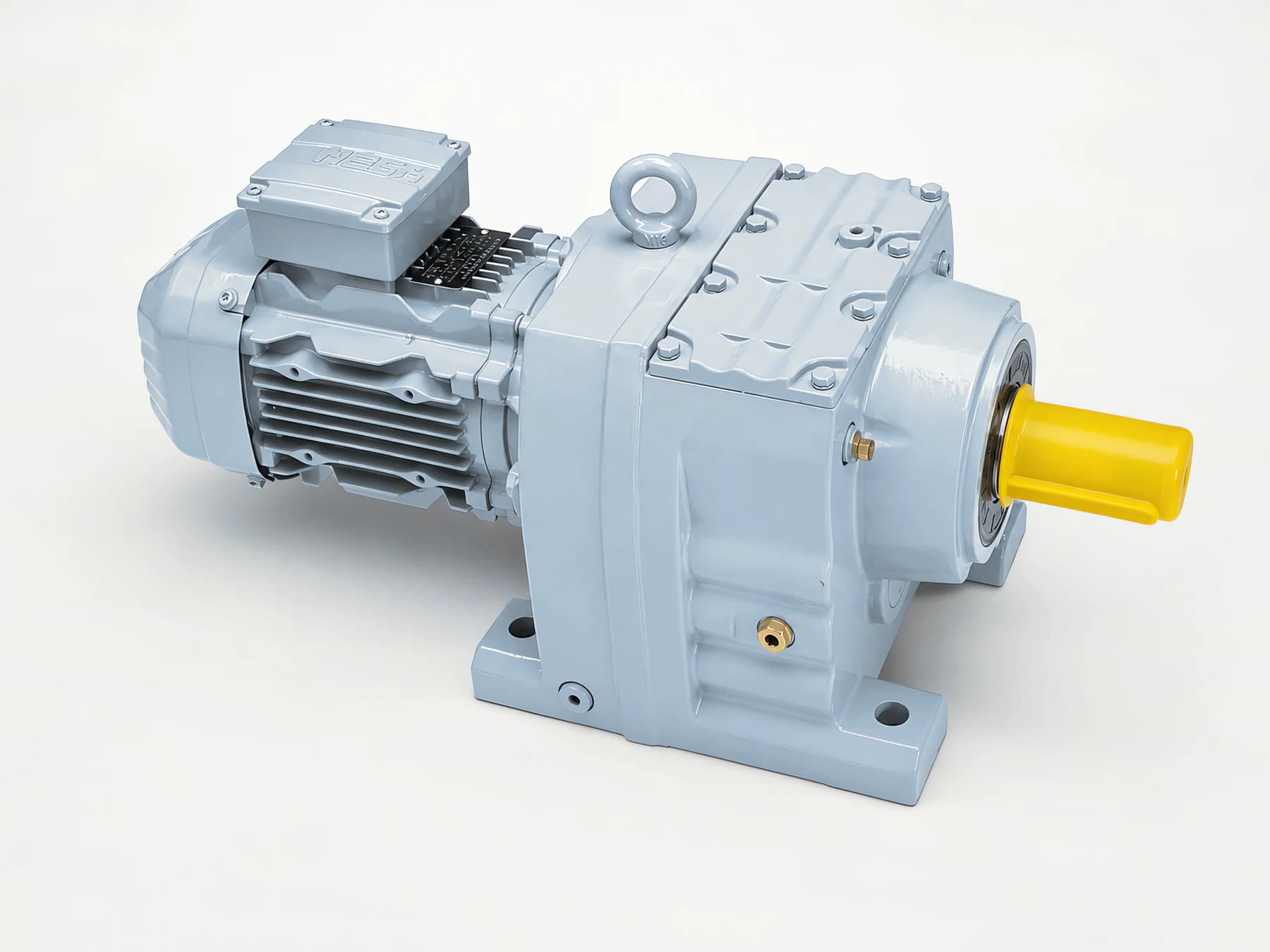
There is no universal minimum frequency. How slow a VFD-driven geared motor can run is decided by whichever of three independent limits gives out first. The thermal limit: a shaft-mounted fan's airflow falls roughly in step with speed, while the copper loss in the windings does not. The torque limit: at low frequency the stator resistance drop takes a larger share of the supply voltage, so available torque falls, and constant-torque loads feel it first. The lubrication limit: splash lubrication needs rotation to throw oil onto the mesh and into the bearings.
The question worth asking is therefore not "what is the lowest frequency" but "which of the three reaches its boundary first in this duty". Asked that way, it has an answer. Asked the other way, it can only produce a number borrowed from somebody else's machine.
Why low speed is harder than it looks
There is an intuition that a slow-turning drive is a lightly loaded one. On an inverter-driven geared motor that intuition fails, and the reason lies in how the motor is cooled.
An ordinary geared motor is self-ventilated: the fan is mounted on the motor shaft at the non-drive end, so it turns only as fast as the rotor. Cooling airflow scales roughly with speed, because it is the same fan turning more slowly. Meanwhile the heat being produced does not follow that curve. The stator copper loss is
P_cu = 3 · I² · RI is phase current, R is per-phase resistance, and the result is in W. Copper loss is set by current. It has no direct relationship with speed. On a constant-torque load the current at low speed is close to the current at rated speed, since the load still asks for roughly the same torque, so the loss stays roughly where it was.
What remains is an asymmetry that holds regardless of any particular frequency: the heat stays about the same while the cooling falls away. The ratio of heat generated to heat removed climbs as speed drops, and the winding temperature rise climbs with it. That is the whole mechanism behind low-speed overheating, and it can be stated without a single number.
Everything below is about finding out which of the three limits that ratio runs into first in a given installation.
The thermal limit
Three things fix where this line sits.
- Cooling method. A self-ventilated motor's heat rejection tracks its speed. A separate blower, or forced ventilation from an independent fan, does not follow the shaft, so its airflow holds up when the motor slows. Two drives running at the same low speed have completely different margins depending on which of the two is fitted. Confirm this before anything else in the selection file.
- Load torque characteristic. A constant-torque load — a conveyor, an extruder screw, a mixer — still asks for close to full torque at low speed, so the current stays high and the copper loss stays high. A variable-torque load with a squared characteristic, such as a fan or a centrifugal pump, sheds torque steeply as speed falls, so its losses fall too, and the margin usually grows rather than shrinks.
- Installation environment. High ambient temperature, restricted space around the frame, and machines mounted side by side all stack onto cooling that is already degraded. A duty that looks acceptable on paper in a test bay can be marginal in a plant room.
One question settles this line better than a table of figures: how much temperature-rise margin does this motor still have at rated speed? A motor that already runs near its limit when it is running at rated speed has essentially nothing left to spend at low speed, and no adjustment on the drive will create margin that the motor does not have. A motor with headroom has something to trade.
The torque limit
Speed follows frequency through synchronous speed and slip:
n_s = 120 · f / p
n = n_s · (1 - s)
n_s is synchronous speed in rpm, f is supply frequency in Hz, p is the number of poles, s is slip, and n is the actual shaft speed.
Torque, power and speed are tied together by:
T = 9550 · P / nP is power in kW, n is speed in rpm, and T is torque in N·m. Read one way, this says that at the same power a lower speed calls for a larger torque. Read the other way, it says that a constant-torque load draws less power as it slows down, which is why the power figure on a nameplate tells you very little about what happens at low speed.
The second half of this limit is not in the load at all; it is in the supply. At low frequency the voltage dropped across the stator winding resistance becomes a larger fraction of the supply voltage, so less is left to build flux and the torque available falls off. That is why low-frequency operation calls for torque boost or for a vector control mode rather than a plain scalar V/f setting. It is not a weakness of one inverter brand; it is what happens when an induction motor is fed at low frequency.
The engineering consequence is straightforward: the constant-torque load is the type that reaches the thermal limit first, and a shortage of torque capability at low frequency makes that arrival earlier and less forgiving. A drive that stalls or trips on overload at low speed is often reporting a torque problem, while the temperature it eventually shows is the thermal limit following behind.
The lubrication limit
This one is easiest to overlook, because it is not on the electrical side at all.
A splash-lubricated gear reducer depends on the rotating gear to throw oil onto the mesh and into the bearings. The slower it turns, the weaker that throw, and the thinner the oil film reaching the contact. Forced lubrication from a pump does not have this dependency, but splash lubrication and oil-bath lubrication do.
That produces a genuinely deceptive failure mode: the motor looks fine and the gearbox is the part in trouble. Frame temperature normal, no overload recorded on the drive, and yet the mesh is short of oil and begins to wear, whine or run hotter than it should. A check that watches motor temperature alone will never see it, which is exactly why it survives so many site visits.
Two things have to be established. First, whether this speed reducer is splash lubricated or force lubricated. Second, if it is splash lubricated, whether the oil supply is adequate at the lowest speed the process actually calls for. And one assumption deserves to be retired: slower rotation does not mean less wear. On a splash-lubricated unit it can mean the opposite, because the oil delivery depends on speed while the load on the teeth may not.
Two more things on the electrical side
PWM output and cable. An inverter output is a high-frequency PWM waveform with a very steep voltage edge. Over a long cable run the travelling wave reflects at the motor terminals and can build an overvoltage there. Longer cable runs and higher carrier frequency make it worse. Cable length, screening and earthing therefore belong in a low-speed review even though they do not set the minimum speed — what they set is long-term insulation reliability, and a failure there is usually diagnosed as an unexplained motor fault.
Shaft current. Common-mode voltage from the drive places a voltage on the shaft. That voltage can break down the oil film in a bearing and complete a current path through the rolling elements, which erodes the raceways over time. It does not depend on speed, but it is specific to inverter drive, and it should be on the list when bearings are inspected — the tell-tale is a washboard pattern across the raceway rather than the usual fatigue spalling.
Continuous low speed is a different application
One general rule is worth keeping. A drive that spends its working life at low frequency should use a VFD-duty motor, one whose cooling and winding insulation are designed around inverter supply rather than around a sinusoidal mains supply. The installation notes in the catalogue make the same point: where the motor is used with an inverter and is frequently operated at low frequency, a VFD-duty motor should be used.
Occasional low-speed running and continuous low-speed running are two different application conditions. A standard motor taken down to low speed for a few minutes at a time during setup or threading is not the same application as one that holds low speed for most of a shift. The answer that suits the first should not be carried across to the second without review.
In what order to check, and why in that order
Work through it as cooling first, torque second, lubrication last. The order is not arbitrary: it runs from the constraint that is quickest to establish to the one most easily forgotten. Cooling and torque can mostly be settled at the desk from the nameplate, the wiring diagram and the load characteristic. Lubrication has to be established from the reducer itself, costs the most time on site, and is the one that gets dropped when a visit runs short.
Being last on the list does not make it optional. On a splash-lubricated unit running slowly it is frequently the first of the three to actually fail, which is why it is written down here rather than left to memory.
| Duty condition | Main risk | Data still needed | Recommended action |
| Self-ventilated motor held at low speed for long periods | Heat rejection falls with speed, temperature rise climbs | Cooling method, temperature-rise margin at rated point, ambient temperature | Assess whether a separate blower or a VFD-duty motor is needed |
| Constant-torque load (conveying, extruding, mixing) | Torque still required at low speed, copper loss does not fall | Load torque characteristic, actual current at low speed | Check against the constant-torque duty, not against power alone |
| Variable-torque load (fans, centrifugal pumps) | Heat falls with speed, margin is usually generous | Whether the load curve is genuinely squared | Some extra latitude is reasonable, but lubrication still has to be confirmed |
| Splash-lubricated gear reducer | Oil supply falls short, wear arrives before motor overheating | Lubrication method, oil level, hours run at low speed | Assess oil supply on its own, or move to forced lubrication |
| Long cable run between drive and motor | Reflected-wave overvoltage, insulation stress | Cable length, screening and earthing arrangement | Handle per the inverter manual — shorten the run or fit an output reactor |
| No torque boost, running scalar V/f | Torque shortfall at low frequency, hard starting or stall | Control mode, whether vector control is available | Move to vector control, or set torque boost per the manual |
| Little temperature-rise margin at the rated point | Almost no margin left at low speed | Measured temperature under rated conditions | Change the cooling arrangement rather than lowering the frequency floor |
| Occasional low speed versus continuous low speed | Two different application conditions | Share of running hours spent at low speed | Select a VFD-duty motor for continuous low-speed duty |
Site checklist
Observable while running
- Record the actual current in the low-speed band and compare it with rated current.
- Record frame temperature and bearing temperature, and compare them with the same readings at rated speed.
- Listen for abnormal noise or periodic rubbing from the gearbox at low speed — an early signal of short oil supply.
- Check the drive's fault log for overcurrent, overload or overtemperature trips.
Requires a shutdown
- Read the motor nameplate: power, number of poles, rated voltage and frequency, rated current, insulation class, cooling method code.
- Confirm the inverter model, the control mode (scalar V/f or vector) and whether torque boost is enabled.
- Confirm the lubrication method of the gear reducer: splash, oil bath or forced.
- Confirm cable length, screening and earthing.
- Inspect the bearings for electrical erosion — a washboard pattern on the raceway.
Must be handled by qualified personnel
- Deciding which of the three limits reaches its boundary first, and stating the low-speed range that can be run.
- Any adjustment touching insulation, carrier frequency or output reactors, carried out by the electrical responsible person following the inverter manual.
Common mistakes and where this guidance stops
Common mistakes
- Applying a "universal minimum frequency" copied from another project. This is the classic one. A different motor, a different cooling method, a different load characteristic and a different lubrication method each move the boundary, so lifting a figure from another installation amounts to transplanting one project's conclusion into another project's duty with none of its evidence. It is the most common mistake in this subject and the one that does the most damage, because the borrowed number carries an air of authority that it did not earn.
- Assuming that a slow drive is a lightly loaded, easier duty. The loss may be unchanged while the cooling has gone.
- Watching motor temperature only and never the gearbox side. A splash-lubricated reducer can fail while the motor still looks perfectly normal.
- Treating a constant-torque load as if it had a squared characteristic, and expecting the margin that a fan duty would have given.
- Running scalar V/f at low speed for months without torque boost, then concluding that the motor is simply weak.
- Leaving a long cable run untreated and treating the resulting insulation failures as random events.
- Having very little temperature-rise margin at the rated point and trying to solve a process problem by lowering the frequency floor.
Where this stops
- The three-limit model and the check order here apply to the inverter-driven duty of R/F/K/S modular geared motors.
- This article gives no minimum frequency value, no derating percentage, no insulation withstand value, no permissible dv/dt, no maximum cable length and no temperature limit of any kind. All of those have to be confirmed by the supplier against the specific model and the specific inverter manual.
- The three limits are a qualitative model. They exist to fix a check order; they do not replace a speed-range verification for a specific model.
- This article does not replace electrical safety design or the inverter manufacturer's installation requirements.
Data checklist for an inquiry
| # | Data item | Note |
| 1 | Motor nameplate data | Power, poles, rated voltage / frequency / current, insulation class, cooling method code |
| 2 | Inverter model and control mode | Scalar V/f or vector; whether torque boost is enabled |
| 3 | Intended speed range | Lowest and highest operating frequency, plus the hours and share of time in each band |
| 4 | Load torque characteristic | Constant torque / constant power / squared torque |
| 5 | Actual current at low speed | A measurement, not a figure back-calculated from power |
| 6 | Cooling method and ambient temperature | Self-ventilated or separate blower; upper ambient limit on site |
| 7 | Whether a separate blower is already fitted | If so, blower data and how it is powered |
| 8 | Lubrication method of the gear reducer | Splash / oil bath / forced |
| 9 | Cable length and screening | Distance from inverter to motor, screening and earthing |
| 10 | Mounting method and space around the frame | Foot or flange; machines mounted side by side, any obstruction to airflow |
| 11 | Measurement points and baseline temperatures | Frame and bearing locations, plus the baseline values recorded at rated speed |
Item 11 is the one most often skipped, and it is the one that decides whether any of the rest can be interpreted. Without a baseline taken at rated speed there is no reference against which to call a low-speed temperature "high". A reading of a warm frame proves nothing on its own; the same reading next to its rated-speed counterpart is evidence.
About this article and the publisher
This article was written by the technical team of Chengfa Reducer (Changzhou) Co., Ltd. (CHINFAR) and released after technical review. The R/F/K/S modular geared motors referred to above are supplied by Chengfa Reducer (Changzhou) Co., Ltd. and are delivered through the joint manufacturing system shared with HUIGUANG.
General overheating troubleshooting and working back from an abnormal temperature to its root cause are covered in two separate articles and are not repeated here:
- R/F/K/S modular geared motors
- Geared motor overheating: causes and a site check order
- Gearbox overheating: working back from the temperature
- Talk to the CHINFAR technical team
Next step
Send the eleven items above to sales@chinfar.com. If the only question is what low frequency the drive can be taken down to, items 1, 2, 4, 6 and 8 are the minimum that has to come with it — they are what locates each of the three limits — and without any one of them no usable answer exists. The speed range we state is subject to engineering review of the actual duty, not to the label on the motor.