 ®

Technical guide
Mechanical Rating vs Thermal Power in an H/B Industrial Gearbox
Author: CHINFAR Technical Team · Reviewer: Tinyuen (CHINFAR) · Updated: 2026-11-04
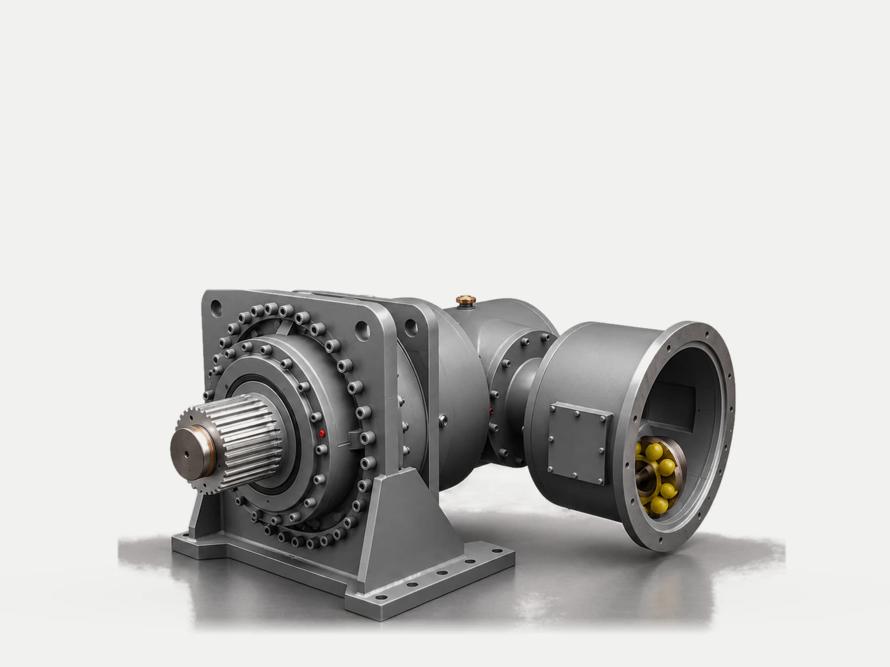
An H/B industrial gearbox carries two limits, and they are not interchangeable. Mechanical rating is set by material and geometry — tooth flank and root strength, bearing life, shaft strength and stiffness — and it barely moves with the weather. Thermal rating is set by heat dissipation, and it falls the moment ambient temperature or altitude rises. The power a unit can actually transmit continuously is therefore the lower of the two:
P_allow = min(P_mech, P_th)The shorthand: mechanical asks "can the teeth take it", thermal asks "can the oil cool down".
Why These Are Two Independent Limits
They come from different physical processes and they fail in different ways.
| Mechanical rating | Thermal rating | |
| Limited by | Flank pitting and tooth breakage, bearing life, shaft strength | Oil temperature reaching its permitted ceiling |
| Set by | Material, heat treatment, face width, module, shaft diameter | Dissipation area, heat transfer coefficient, ambient temperature |
| Failure mode | Pitting, tooth fracture, bearing spalling | Oil degradation, seal ageing, viscosity loss |
| Response to ambient conditions | Essentially unchanged | Changes substantially |
| Cost of oversizing | Volume, weight, cost | Additional cooling equipment required |
The last two rows are the key. A unit on a northern site in midwinter and the same unit on a southern site in midsummer have almost the same mechanical rating — but their thermal ratings can be far apart. Select on the mechanical side alone and that unit will be running hot, derated or tripping alarms by summer.
Where the Thermal Rating Comes From
The thermal rating is not a number lifted from a table. It has an explicit derivation chain.
Step 1 — the heat comes from power loss.
P_loss = P_in · (1 − η)P_in is input power, η is efficiency, and P_loss is the power converted into heat.
Step 2 — dissipation depends on area and temperature difference.
Q_diss = k · A · ΔTk is the heat transfer coefficient, A is the dissipation area, and ΔT is the difference between oil temperature and ambient temperature.
Step 3 — thermal equilibrium: heat generated equals heat dissipated.
P_in · (1 − η) = k · A · ΔTStep 4 — solve for the thermal rating.
P_th = k · A · ΔT / (1 − η)The temperature difference itself is:
ΔT = T_limit − T_ambientT_limit is the permitted oil temperature ceiling and T_ambient is ambient temperature.
That chain settles the point: the thermal rating is not an intrinsic property of the unit. It is the capacity that unit has at a given ambient temperature. Change the ambient, and the number changes with it.
Ambient Temperature and Altitude Press Only on the Thermal Side
Two things follow directly from the P_th expression.
Ambient temperature rises → `ΔT` shrinks → `P_th` falls. This is the intuitive one: summer is harder than winter not because the gearbox got worse, but because the available temperature difference got smaller.
Altitude rises → air thins → heat transfer coefficient `k` falls → `P_th` falls. This one is easier to miss, because nothing visible changes on site — only the density of the air. A high-altitude project selected on sea-level data will end up tight on the thermal side.
Mechanical rating is largely insensitive to both. That is the entire distinction: one capacity depends on the environment, the other depends on the structure.
What Sets the Mechanical Rating
The mechanical side is four checks, and the first one to reach its limit governs.
| Element | Limiting mechanism |
| Tooth flank contact strength | Contact stress too high → pitting |
| Tooth root bending strength | Bending stress too high → tooth fracture |
| Bearing life | Load and speed set the calculated life |
| Shaft strength and stiffness | Combined bending and torsion; deflection disturbs the mesh |
All four are fixed at the design stage by material, heat treatment, face width, module, shaft diameter and bearing selection. They do not move with the weather.
The Service Factor System: An Institutional Corroboration
One detail of the selection system is worth stating, because it corroborates the distinction this article is making.
Under the ReducerDB selection rules:
- R/F/K series — total service factor
f = f1 · f2 - S series — total service factor
f = f1 · f2 · f3, where `f3` is the ambient temperature factor
R/F/K:  f = f1 · f2
S:      f = f1 · f2 · f3
Why does the S series carry one more factor? Because it turns the effect of ambient conditions on capacity into an explicit reduction. The R/F/K series describes duty through f1 (type of driven machine and hours loaded per day) and f2 (starts per hour); ambient temperature does not appear separately in that factor system.
This is not a claim that the R/F/K series ignores ambient temperature. It is a claim about the system: inside the S series, ambient temperature is formally recognised, so it must be multiplied in separately at selection.
The selection criterion is:
Choose the size from the selection tables by running power and output speed, and ensure the calculated total service factor does not exceed the service factor given in the selection tables.
The value of f3 must be looked up in the selection tables against the actual ambient temperature. It is not given here.
Which One Is in Control
The method is direct: calculate both requirements, and the larger one is the controlling one.
| Situation | What is in control | What to do |
| Low speed, heavy load, mild ambient | Mechanical rating | Select on mechanical capacity; verify flank and bearings |
| High speed, high ambient temperature | Thermal rating | Select on thermal power, or add cooling |
| High speed, high ambient temperature, high altitude | Thermal rating (doubly reduced) | Cooling scheme first |
| Long-term continuous running | Thermal rating (no cooling interval) | Check thermal equilibrium for the continuous case |
| Intermittent running with real cooldown time | Mainly mechanical rating | But still check the worst continuous stretch |
The intermittent case needs care. Intermittent duty means there is shutdown time to shed heat, so equilibrium may never be a problem — but if any one stretch has to run continuously, that stretch is the governing thermal case, not the average of the shift.
The Cooling Decision Tree
When the calculation gives P_loss > Q_diss — heat generated exceeding heat dissipated — four routes exist:
P_loss > Q_diss ?
  ├─ no  → thermal side is not the constraint; select on mechanical capacity
  └─ yes → four options:
       ├─ 1. larger housing (increase dissipation area A)
       ├─ 2. add a fan (increase heat transfer coefficient k)
       ├─ 3. add an oil cooler (raises k substantially; needs supporting hardware)
       └─ 4. reduce load or improve ventilation (lower P_loss or raise k)
The trade-offs:
| Option | Advantage | Cost |
| Larger housing | Solved once, no external equipment | Volume, weight and cost all rise |
| Fan | Cheap and structurally simple | Only effective in moderate ambient; needs maintenance in dusty plant |
| Oil cooler | Strong cooling capability | Needs pump, piping, maintenance; leak risk |
| Reduce load / improve ventilation | No equipment change | Limited by process; ventilation gains are finite |
Order of attack: check first whether ventilation can be improved (cheapest), then consider a fan, then whether a larger housing is unavoidable, and only last an oil cooler (highest system complexity).
Condition Table
| Site observation | Likely cause | Data still needed | Suggested action |
| Fine in winter, overheats in summer | Higher ambient temperature shrinking ΔT | Peak summer ambient temperature | Recheck thermal power for summer conditions |
| Fine at sea level, overheats at altitude | Lower air density reducing k | Altitude | Recalculate thermal power with the altitude correction |
| Low speed and heavy load, yet oil stays cool | Mechanical side is in control | Flank and bearing check results | Select on mechanical capacity |
| High speed and light load, yet overheats | Thermal side is in control | Efficiency, dissipation area, ventilation | Check thermal equilibrium; consider cooling |
| Intermittent running fine, continuous running overheats | No shutdown time to shed heat | Longest continuous running period | Check against the worst continuous stretch |
| Oil temperature rose after an oil change | Viscosity or oil quantity changed | Oil grade and fill quantity | Recheck oil grade and oil level |
| Still overheats after a fan was added | Ambient too high or dissipation area too small | Ambient temperature, housing size | Consider a larger housing or an oil cooler |
| Output bearing damaged | Possibly radial or axial load over the limit | Measured radial and axial loads | Check bearing loads separately, see the load article |
Field Checklist
At selection:
- Establish the running power
Pand the output speed. - Establish the driven machine type and the hours loaded per day (for
f1). - Establish the starts per hour (for
f2). - Confirm whether the unit falls under the S series system — if so, the ambient temperature factor
f3must be included. - Collect the ambient temperature range, using the maximum, not the average.
- Confirm the altitude.
- Confirm the mounting arrangement and ventilation (indoor, outdoor, enclosed space).
At verification:
- Select the size on mechanical capacity and verify flank and bearings.
- Check thermal power at the most adverse ambient temperature.
- Compare
P_losswithQ_dissto decide whether cooling is needed. - Check output radial and axial loads separately.
After commissioning:
- Record actual oil temperature under summer or high-altitude conditions as the basis for later review.
Common Mistakes and Where This Article Stops
Common mistakes:
- Selecting on mechanical capacity only, with no thermal calculation. It can look fine in winter and at low altitude, and then fail in summer or on a plateau.
- Calculating thermal power with the average ambient temperature. The most adverse — the maximum — is the one to use.
- Ignoring altitude. Lower air density weakens dissipation directly.
- Treating the thermal rating as a fixed property of the unit. It is a capacity at a given ambient; change the ambient and it changes.
- Sizing an intermittent-duty unit on continuous duty (over-designed), or a continuously running unit on intermittent duty (under-designed).
- Improving ventilation without rechecking fan type and dust maintenance.
- Ignoring radial and axial loads. They are a separate limit outside mechanical capacity and must be checked on their own.
Where this article stops:
- The two-limit distinction, the formulas, the ambient-sensitivity analysis and the cooling decision apply to selection checks on H/B industrial gearboxes and general-purpose reducers.
- This article gives no mechanical rating values, no thermal power values, no heat transfer coefficient or dissipation area values, and no altitude correction figures.
- It gives no numerical value for the `f3` ambient temperature factor — that must be looked up in the selection tables against the actual ambient temperature.
- It does not quantify where selection problems "mostly" come from; it gives the distinction between the two limits and the method for judging which one applies.
- A specific selection must follow the product selection tables and the requirements of the individual machine. This article does not replace a check calculation for a specific project.
Selection Input Checklist
| No. | Input | Why it matters |
| 1 | Running power | What the driven machine actually requires |
| 2 | Output speed | Sets the size and the thermal duty |
| 3 | Driven machine type | Used to determine f1 |
| 4 | Hours loaded per day | Used to determine f1 |
| 5 | Starts per hour | Used to determine f2 |
| 6 | Whether the S series system applies | If so, f3 must be included |
| 7 | Maximum ambient temperature | The maximum, not the average |
| 8 | Altitude | Affects the heat transfer coefficient |
| 9 | Mounting and ventilation | Indoor, outdoor or enclosed |
| 10 | Longest continuous running period | The governing thermal case |
| 11 | Output radial and axial loads | Must be checked separately |
Items 7 and 8 are the two most easily missed: neither affects mechanical capacity, both press on thermal power — so a mechanical check alone shows nothing about them.
About This Article and the Publisher
This article was written by the Chengfa Reducer (Changzhou) Co., Ltd. (CHINFAR) technical team and released after technical review. The H/B series industrial gearboxes are supplied by Chengfa Reducer (Changzhou) Co., Ltd.; CHINFAR products are built and delivered on the joint manufacturing system shared with HUIGUANG.
Related pages:
- H/B series industrial gearboxes
- H/B series industrial gearbox application overview
- Gearbox overheating: tracing a temperature fault back to its cause
The overheating article is diagnosis: the unit is already hot, so why. This one is selection: which of the two limits applies, and how each is established. The two run in opposite directions and complement each other rather than overlap.
Next Step
Send the eleven items above to sales@chinfar.com. If the project sits in a hot region or at altitude, state items 7 and 8 explicitly — they leave the mechanical check untouched while pressing only on thermal power, and a mechanical check alone will never show them.
One point to be clear about: this article gives no rating values and no environmental correction factors. A specific selection must follow the product selection tables and the requirements of the individual machine, and output radial and axial loads still require a separate check.