 ®

Technical guide
How to Arrange a Torque Arm on a Hollow-Shaft Gearbox
Author: CHINFAR Technical Team · Reviewer: Tinyuen (CHINFAR) · Updated: 2026-11-04
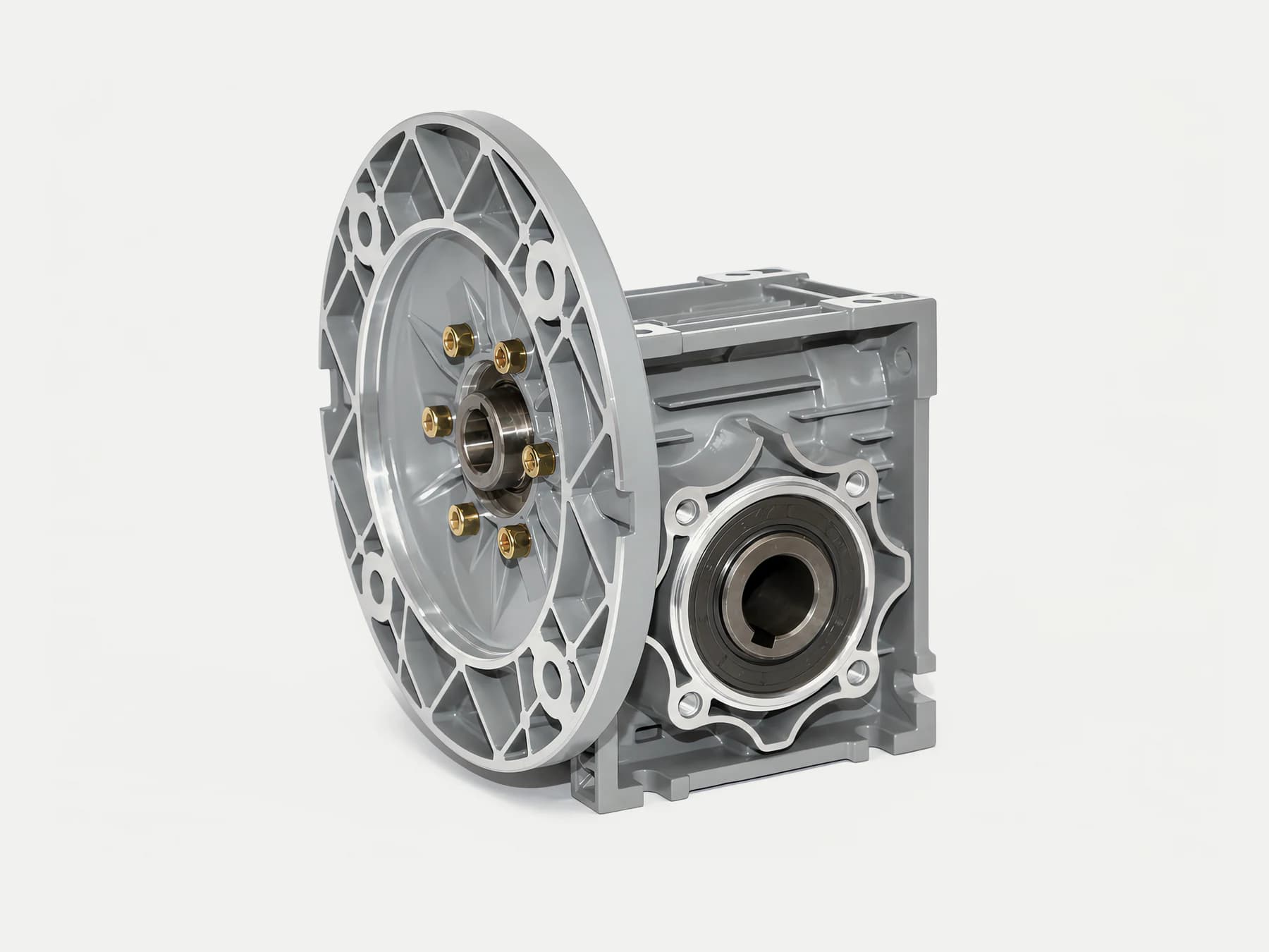
A torque arm does exactly one job: it carries the reaction torque so the hollow-shaft gearbox cannot spin around the driven shaft. Everything else must be free. The rule is one sentence: constrain one degree of freedom, rotation about the driven shaft, and release the other five. Axial float, small radial movement and angular misalignment all need room. Fit feet, weld the arm solid, or force it into position, and the gearbox ends up over-constrained: the extra bending moment loads the bearings and shaft, showing up as noise, oil leaks and early bearing failure.
What the torque arm is actually holding back
The output of a hollow-shaft gearbox is a bore, not a shaft end. The unit slides onto the driven shaft and transmits torque through that bore.
The difficulty is this. While the gearbox applies torque to the driven shaft, it receives an equal and opposite reaction torque. Nothing on the unit absorbs it. There are no feet, so the driven shaft is the only thing carrying the gearbox. The unit therefore tries to rotate around that shaft and throw its own housing round with it.
The torque arm is the abutment that stops it. It passes the reaction torque into the frame and keeps the gearbox where it belongs.
So the arm carries torque, not weight. That single fact settles every design decision that follows: the arm does not have to be built like a support leg, but its fixing point must take the reaction force, and it must allow the gearbox to float slightly on the driven shaft.
The force in the arm depends on its length:
F_arm = T_out / L_armT_out is the output torque (N·m), L_arm is the lever arm from the point where the reaction force acts to the axis of rotation (m), and F_arm is the force carried by the torque arm and its fixing point (N). The practical reading is blunt: the shorter the arm, the higher the force at the fixing point for the same torque. Shortening the arm because space is tight is often where loose fixing bolts or a torn frame begin.
Reaction direction: forward and reverse are two directions
The reaction torque always acts opposite to the output torque. In engineering terms that means:
- running forward, the arm takes the reaction one way;
- running in reverse, it takes the reaction the other way.
For equipment that reverses, two things follow:
- The arm and its fixing point must be designed for bidirectional load, not just for the main direction of rotation.
- The fixing method — bush, bolts, frame connection — must not depend on one-way thrust.
In the dimension tables for the hollow-shaft variants, the catalogue distinguishes two mounting directions for the anti-rotation arm: C side and D side. The side you choose follows the direction of the reaction, and it is not a matter of picking whichever face is easier to reach. Which side belongs to which direction of rotation has to be confirmed against the catalogue and the specific model.
The degree-of-freedom rule: constrain one, release five
This is the core of the subject. Take the six degrees of freedom of the hollow-shaft unit one at a time:
| Degree of freedom | Constrain? | Why |
| Rotation about the driven shaft | Must be constrained | This is the only reason the arm exists |
| Axial movement along the driven shaft | Must be released | The shaft grows with heat, and assembly needs float |
| Radial movement, horizontal | Must be released | Small eccentricity between shaft and bore has to be accommodated |
| Radial movement, vertical | Must be released | Same reason |
| Rotation about the radial horizontal axis (pitch) | Must be released | Angular misalignment must be allowed |
| Rotation about the radial vertical axis (yaw) | Must be released | Angular misalignment must be allowed |
One line to remember: constrain one, release five.
Why must those five be released? Because a hollow-shaft unit is located by the driven shaft. The connection between bore and shaft is a fit, and a fit of that kind already permits — and needs — a little axial float and angular compensation. If the arm locks those out as well, the gearbox and the shaft become over-constrained: two rigid constraints demand that the same part sit in two places at once, and the part pays for it with an internal bending moment.
The bending moment does not disappear. It:
- loads the bearings at the gearbox output off centre;
- adds bending stress to the driven shaft;
- shows up in service as noise, vibration, seal wear and oil leaks, and ends as early bearing failure.
Over-constraint: the most common fatal mistake
Three practices account for most over-constraint, in order of how often they occur.
First: feet as well as a torque arm. This is the classic. A hollow-shaft unit should not have feet at all — the driven shaft is what locates it. Add a set of feet and the gearbox gains a second rigid locating point, and the two can never line up perfectly. The housing ends up twisted and the bearings run off centre for the rest of their life.
Second: the arm welded solid, or bolted rigidly to a stiff frame with no bush in between. The reaction does get out, but the frame's deflection, its vibration and the installation error come straight back into the gearbox at the same time.
Third: the arm forced into position during assembly. The fixing point on the frame is slightly off, so the arm is levered or jacked across until the holes line up, then tightened. That builds a bending moment into the assembly before the machine has even run; the reaction adds to it in service and the trouble arrives quickly.
The test is simple, and you can run it on site. After installation the gearbox should be able to shift slightly within its free play. If it cannot move at all, it is almost certainly over-constrained.
Bushes: why a rigid fixing fails
An elastic bush at the arm's fixing point does two things:
- It absorbs vibration. The gearbox and the frame are two separate vibrating systems, and a rigid connection passes vibration from one to the other in both directions.
- It absorbs small displacement. It lets the gearbox float on the driven shaft in the way the fit already allows.
A bush is not a case of softer is better. Its specification has to be matched to the actual reaction force: too soft and the reaction cannot get out, so the arm swings; too stiff and it may as well not be there, and the connection is rigid again. The bush has to be selected by the supplier for the model and the reaction force — a piece of rubber mat is not a substitute.
Some installations use a torque arm in the form of a tie rod with a ball joint at each end. The idea is identical: the joints release the angular freedoms and only rotation is constrained.
Fasteners and locking
The bolts in a torque arm see alternating shear or tension and compression, not a static load. Therefore:
- tighten them to the specified torque and property class, and do not substitute ordinary bolts for high-strength ones;
- apply a positive locking method — lock washers, thread locking compound or self-locking nuts;
- re-torque after the first period of running, then put the check on the periodic inspection list.
Re-torquing is the step most often skipped. A newly installed arm settles slightly in the first hours of running, preload drops, and without a re-torque the sequence is loosen, impact, loosen faster.
There is also a hard limit. Never replace the torque arm with chain, wire rope, straps or anything similar. Those carry tension only. They cannot carry a reversing reaction, they fail as soon as the drive reverses, and when they fail the gearbox can spin free at speed. That is a direct risk to people, not a maintenance inconvenience.
Condition table
| Installation condition | Main risk | Information needed | Recommended action |
| The equipment reverses | Reaction changes direction; a one-way fixing fails | Direction of rotation and reversing frequency | Design for bidirectional load and confirm the mounting side |
| Space is tight, so the arm gets shortened | Force at the fixing point rises steeply | Available arm length, output torque | Check the fixing point with F_arm = T_out / L_arm |
| The frame already has foot holes | Feet get fitted by mistake and over-constrain the unit | Whether the original design used feet | Fit no feet on a hollow-shaft unit; the arm alone |
| The frame is stiff and vibration is noticeable | Vibration passes straight back into the gearbox | Source and frequency of the vibration | Fit an elastic bush at the arm's fixing point |
| The driven shaft has thermal growth | Axial movement locked out, extra axial force | Operating temperature, shaft length | Keep axial float available |
| The fixing point position is off at installation | Bending moment built in during assembly | Measured position of the frame fixing point | Adjust the frame or open up the holes; never force the arm across |
| Frequent removal for maintenance | Every strip and rebuild disturbs the float | How often it is dismantled | Choose a jointed arm that relocates repeatably |
| Concrete or thin-wall frame | Local crushing or tearing at the fixing point | Frame material and plate thickness | Add a spreader plate, and stiffen if required |
Site checklist
Before installation
- Measure the driven shaft diameter and its actual tolerance, and confirm the fit with the hollow bore is acceptable.
- Check the reversing requirement and decide whether the arm has to be designed for both directions.
- Confirm the mounting side of the anti-rotation arm for this model — C side or D side — matches the direction of the reaction.
- Check that the frame fixing point lines up with the arm on the gearbox; if it does not, change the frame first.
During installation
- Fit no feet — this is a hollow-shaft unit.
- Confirm an elastic bush or a jointed connection is in place between the arm and the frame.
- Tighten to the specified torque and property class, and lock the fasteners.
- Check that the gearbox can float slightly within its allowance and has not been locked solid.
After installation, first run
- Run forward and in reverse and watch the arm for abnormal impact or movement.
- Check the arm's fixing bolts for any sign of loosening.
- Re-torque after the first running period and add the check to the maintenance schedule.
Common mistakes and applicability limits
Common mistakes
- Fitting feet and a torque arm together. This is the over-constraint to avoid above all others on this page.
- Welding the arm solid, or clamping it straight onto the frame with bolts and no elastic bush.
- Levering the arm into position with a pry bar and then tightening, so a bending moment is built in during assembly.
- Designing the arm for one direction only, then having the fixing point fail when the drive reverses.
- Shortening the arm to suit a tight space without checking the fixing point against
F_arm = T_out / L_arm. - Replacing the arm with chain, wire rope or straps.
- Skipping the re-torque and leaving the arm off the inspection list, so loose bolts are found late.
Applicability limits
- The arrangement rule, the degree-of-freedom table and the condition table apply to torque arm installation on hollow-shaft (shaft-mounted) gearboxes.
- This article gives no torque arm dimensions, no arm lengths, no bore sizes, no bolt specifications, no tightening torques and no reaction-force values. These have to be confirmed by the supplier for the specific model and the current catalogue.
- The C side and D side descriptions of the anti-rotation arm come from the product catalogue; which one corresponds to which direction of rotation must be checked against the catalogue and the model.
- For a specific model, the installation manual supplied with the unit governs; this article does not replace it.
- This article does not replace a safety review for the equipment concerned.
Installation data checklist
| No. | Item | Note |
| 1 | Driven shaft diameter and measured tolerance | A nominal size on its own is not enough |
| 2 | Shaft surface condition | Rust, scoring, coating |
| 3 | Output torque and peak torque | Give steady-state and peak separately |
| 4 | Direction of rotation | One direction or reversing; if reversing, the reversing frequency |
| 5 | Position of the arm's fixing point on the frame | Measured coordinates, or the distance from the rotation axis |
| 6 | Available arm length | This sets the force at the fixing point |
| 7 | Whether an elastic bush is needed | If so, state where the vibration comes from |
| 8 | Installation and maintenance space | Axial float allowance, room to dismantle |
| 9 | Ambient conditions | Temperature, dust, moisture, vibration |
| 10 | Existing frame material and plate thickness | Decides whether a spreader plate or stiffening is needed |
Items 5 and 6 are the two most often skipped: the position of the fixing point sets the arm length, and the arm length sets the force. Plenty of enquiries say only that a torque arm is wanted, without saying how far the arm can reach. The supplier can then offer only a general part, and the site has to make it fit — and making it fit is very often where over-constraint comes from.
About this article and the publisher
This article was written by the technical team of Chengfa Reducer (Changzhou) Co., Ltd. (CHINFAR) and published after technical review by the company. The H/B series industrial gearboxes referred to here are supplied by Chengfa Reducer (Changzhou) Co., Ltd.; CHINFAR products are delivered through the joint manufacturing system shared with HUIGUANG.
Mounting positions and first-run checks are covered in separate articles and are not repeated here:
- H/B series industrial gearboxes
- Gearbox mounting positions M1–M6, and which parameters change with them
- Industrial gearbox installation, lubrication and first-run checklist
Next step
Send the ten items above to sales@chinfar.com. If you want to answer only one question first, answer item 4: does this machine reverse? That decides whether the arm is designed for one direction or two, and it also decides which mounting side you choose.
Selection and installation proposals are subject to engineering review. This article does not replace the installation manual for the machine, and it does not replace a safety review for the specific equipment covered.