 ®
®Technical guide
Gearbox Mounting Positions M1 to M6: What Changes and Why It Matters
Author: HUIGUANG × CHENGFA Transmission Technical Team · Updated: 2026-09-11
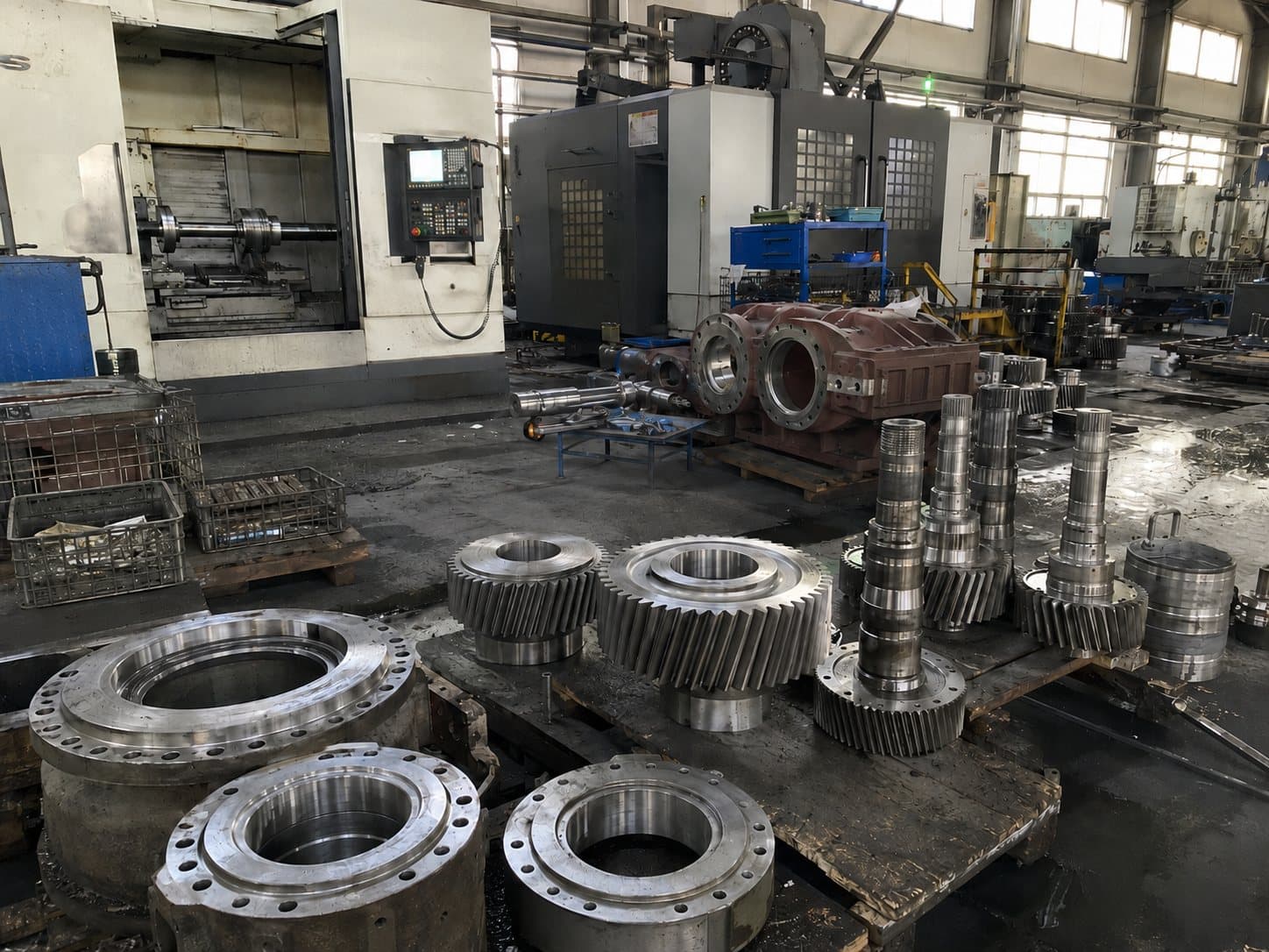
Mounting position is one of the selection parameters that most often gets underspecified. Many buyers treat it as an afterthought, then find at installation that the breather is on the wrong face, the drain plug is buried under the baseplate, or the oil level reads wrong because the sight glass is at the high side of the casing rather than the operating level.
What mounting position actually controls
Four items follow the mounting position: oil fill quantity, breather and drain plug location, oil sight glass position, and the orientation that defines the operating oil level. Mounting position does not change torque, ratio, service factor — it changes the support conditions around them.
The six standard positions
M1 to M6 is the convention used by the modular helical, parallel-shaft, helical-bevel and helical-worm families. The reference convention is: M1 is the horizontal foot-mounted position with the input shaft horizontal and the output shaft horizontal. M2 rotates the gearbox 90 degrees around the input axis. M3 places the gearbox with the input shaft vertical (downward). M4, M5 and M6 cover the remaining 90-degree steps around the input axis.
- M1: foot-mounted, input horizontal, output horizontal — the default catalogue configuration.
- M2: foot-mounted, input vertical (upward), output horizontal — used when the motor sits above the gearbox.
- M3: foot-mounted, input horizontal, output vertical (downward) — common in mixers and vertical agitators.
- M4: flange-mounted, output upward — used where the driven shaft goes up into the machine.
- M5: flange-mounted, output downward — common in top-driven mixers where the gearbox hangs from the motor platform.
- M6: foot-mounted with the input/output geometry of M3 but rotated 180 degrees about the foot axis.
Why oil fill is position-dependent
Oil quantity is not a fixed value per gearbox model. The fill that gives the right oil level at M1 is too low at M3 (where the oil has to cover a different set of gears and bearings) and too high at M5 (where it floods the breather). The sample data sheet lists oil quantities for M1, M2, M3, M4, M5 and M6 separately — confirm the exact fill from the factory-fitted drawing for the position you are installing.
Common installation mistakes by position
- Installing at M3 without rotating the oil sight glass — oil level reads wrong and the unit either runs starved (low oil) or overfilled (oil foaming at the breather).
- Forgetting to relocate the breather when going from M1 to M2 — the standard breather ends up below the oil level and the gearbox pressurizes through the seals.
- Leaving the drain plug on the wrong face after a position change — drain at the next oil change becomes a half-day job of removing the gearbox from the baseplate.
- Ordering M4 or M5 flange mounting without specifying the flange orientation relative to the output — the gearbox arrives with the flange rotated 90 degrees to the driven shaft.
- Treating M3 as interchangeable with M6 — the oil-fill table is not symmetric across these two positions.
When mounting position drives the gearbox choice
If the application calls for a vertical output (M3 or M5), the choice between F-series parallel-shaft and K-series helical-bevel is rarely free. K-series offers a right-angle output with lower overhung load on the driven shaft; F-series parallel-shaft cannot be mounted vertical without a special flange adapter and reduced service factor. Confirm the vertical-output envelope with the factory drawing before ordering.
Service factor and position interaction
Some position-mount configurations impose additional thermal or load penalties. A gearbox operating in M3 with a high-output overhung load can run hotter than the same gearbox in M1 because the oil splash pattern is less effective at reaching the upper bearings. The lubrication guide documents the recommended fill and viscosity for each position; the service factor should be confirmed against the actual position.
What to confirm before ordering
Provide the mounting position, the orientation of the driven shaft, the overhung load (if any), and the desired breather and drain location. The factory-fitted configuration will be set to the position requested, and the oil-fill table from the factory drawing is the value to use at first fill and at every oil change thereafter.
For project-specific mounting configurations, send the layout drawing and the driven-machine interface dimensions to sales@chinfar.com.