 ®

Technical guide
How Radial and Axial Loads on the Gearbox Output Shaft Affect Selection
Author: CHINFAR Technical Team · Reviewer: Tinyuen (CHINFAR) · Updated: 2026-11-04
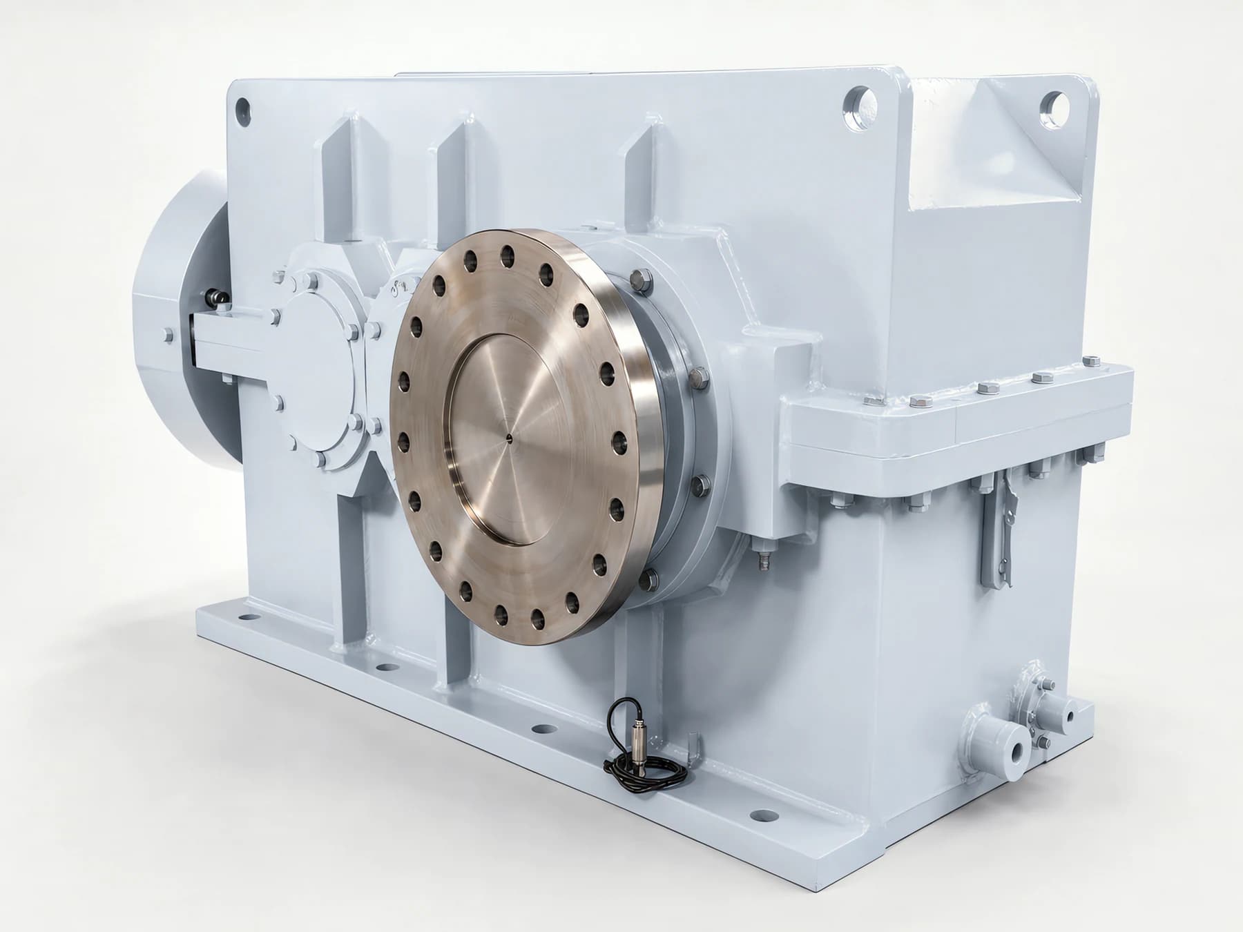
Radial and axial forces on an output shaft are not two extra numbers to drop into a data sheet. Each becomes checkable only when it travels with its point of application: on one gear reducer, a load at the shaft end and a load of equal size close to the shaft shoulder are permitted to be different in magnitude. Axial force must first be split by direction — pushing into the reducer or pulling away from it — and by origin, then checked jointly with the radial force.
A specification line that states a radial force and stays silent on the overhang cannot be verified at all, and where a radial and an axial force act at once, neither may be signed off on its own.
Three quantities, and the one most often misplaced
| Quantity | Definition | Unit | Note |
Radial force F_r | A force perpendicular to the output shaft axis, acting on the shaft extension | N | The transverse force a pulley, sprocket, gear or agitator impeller puts on the shaft |
Axial force F_a | A force along the output shaft axis | N | The axial component of a helical or bevel gear or a worm drive, or an external push or pull |
Overhang L | The axial distance from the shaft shoulder (the locating step on the shaft) to the load application point | mm | The quantity most often left out, and the one most often measured from the wrong datum |
The first two say how large a force is. The third says where it lands. What decides whether a shaft survives is the bending moment that force and position produce together, not the force by itself.
Where the overhang is measured. The datum is the locating face of the shaft shoulder, not the tip of the shaft. The end point is the resultant of the load: the mid-width of a pulley, the mid-face width of a sprocket, the mid-face width of a gear, the midpoint of a coupling, the equivalent acting point of an impeller. The classic mistake is to start the tape at the protruding shaft end. That shortens the measured overhang, and a shortened overhang is what an undersized selection is built on.
A radial load without its point of application is not a checkable quantity. It is not a conservative omission and it is not a detail to be settled later at the drawing stage — it removes the only term that converts a force into a duty the bearing and the shaft can be judged against.
Where the forces come from: three conversions
Most forces on an output shaft are not measured directly. They are converted from the transmitted torque and the geometry of whatever is mounted on the shaft.
Peripheral force, from transmitted torque and the effective diameter:
F_t = 2000 · T / dT is the transmitted torque in N·m, d is the pitch circle or hub diameter in mm, and F_t comes out in N.
Radial separating force of a spur gear pair:
F_r = F_t · tan αα is the pressure angle, in degrees, and F_r comes out in N.
A helical gear pair carries an axial component as well:
F_a = F_t · tan ββ is the helix angle at the reference circle, in degrees, and F_a comes out in N. For a spur gear β is zero, so the axial component is zero too. That is exactly why the same power at the same speed, moved onto a helical gear pair, leaves the output shaft carrying an axial load it did not carry before — and why the bearing arrangement has to change with it.
Belt and chain drives need separate treatment. The shaft load has to be built from the tight-side and slack-side tensions combined by geometry. It may not be replaced by the peripheral force back-calculated from torque. A belt runs with two sides at unequal tension, and the vector sum of those tensions is normally larger than the peripheral force. Reporting a pulley load as a peripheral force is one of the most common ways a shaft load ends up underestimated, and the error is invisible afterwards because the figure looks like a properly derived one.
How to read an allowable load curve
The "allowable radial load" in a catalogue is never a single isolated figure. It is a curve against overhang, usually anchored at a value quoted for a reference distance.
One relationship is enough to read it. The bending moment at the root of the output shaft:
M = F_r · LWithin the range where bearing life governs, an equal-moment conversion is a fair approximation:
F_allowed(L) ≈ F_ref · L_ref / LHere F_ref is the allowable value at the reference distance L_ref, and L is the actual overhang. The meaning is blunt: double the overhang and the allowable radial force roughly halves. That conversion applies while bearing life is the governing factor; where shaft strength is the governing factor, the case has to be checked separately and the result of the conversion cannot be carried over.
That conversion holds only while bearing life governs. Two boundaries have to be stated with it, and both are routinely dropped:
- It is valid in the bearing-life-governed range only. When the overhang is short and the load is large, the governing criterion shifts from bearing life to the bending strength of the shaft. In that range the conversion no longer applies, and the shaft strength check takes over. Applying the equal-moment conversion where shaft strength governs produces an allowable value that nothing supports.
- It is valid only where the load direction matches the reference condition. A load biased toward a particular azimuth leaves the bearing with a different capacity, and the actual direction has to be reviewed rather than assumed.
So the correct reading is three steps: confirm which point the reference distance is measured to, convert your own overhang onto the reference basis, and confirm whether the bearing or the shaft is the governing element. Lifting the headline figure off the curve and comparing it with your F_r — no conversion, no check on what governs — is the most common misreading of these curves.
Radial and axial, checked together
When a radial force and an axial force act at the same time, they cannot be judged separately, each against its own limit. Acting together they change both the equivalent bearing load and the stress state in the shaft, so the check has to be a combined one.
The axial side itself splits into two questions that are often conflated:
- Direction. Pushing toward the gear reducer or pulling away from it. The same bearing arrangement does not carry equally well in both directions, so magnitude alone is not enough information.
- Origin. An internal axial component generated by the gear mesh, or an axial load imposed by external equipment. The two behave differently: a mesh component rises and falls with torque, while an external axial load may be constant or alternating and need not follow torque at all.
One rule of thumb is worth keeping: if the axial force comes from a helical or bevel mesh, it shares a source with the radial force and moves in step with it. If it comes from outside — a screw conveyor, a pressure thrust — it has no fixed relationship to torque, and the duty has to be described on its own terms.
Condition-by-condition judgement
| Duty condition | Main risk | Data still needed | Recommended action |
| Pulley or sprocket on the shaft | Peripheral force substituted for the real shaft load, so the load is underestimated | Tight-side and slack-side tensions, wrap angle, wheel diameter | Combine the two tension components; do not report F_t |
| Long overhang | Bending moment overshoots, bearing life falls away sharply | Shoulder position, distance from the load point to the shoulder | Recheck with M = F_r · L and convert the allowable value |
| Short overhang with a heavy load | Governing criterion shifts from bearing to shaft strength | Load magnitude, shaft diameter, material | Switch to a shaft strength check; do not carry the equal-moment conversion across |
| Helical or bevel gear output | The axial component is ignored | Helix or cone angle, hand of rotation | Include it via F_a = F_t · tan β and check jointly |
| Axial direction not established | Wrong bearing arrangement selected | Thrust direction, whether it acts both ways | Confirm push and pull as two separate cases |
| Alternating or shock loading | Fatigue and peak coexist | Load spectrum, source of the shock factor | Run the peak check and the fatigue check separately |
| Shrink disc or coupling at the shaft end | Usable overhang and mounting length are constrained | Connection type, hub length, installation space required | Confirm the usable shaft extension against the connection type |
| Agitator, scraper or other long-shaft duty | Very long overhang plus a sideways force from the medium | Shaft length, impeller diameter, medium, presence of a steady bearing | See the dedicated agitator article and review separately |
Site checklist
Observable while running
- Visible radial runout or whipping at the shaft end, especially as load is applied and removed.
- Bearing temperature rising noticeably faster than load rises.
- Belt wear concentrated on one side, or belt tracking drift — uneven wear usually means the actual load direction differs from the design assumption.
- Periodic noise or vibration that tracks shaft speed.
Requires a shutdown
- Measure the shoulder position and the distance from the load application point to the shoulder — not to the shaft end.
- Record the type of component on the shaft, its wheel diameter or face width, and its mounted position.
- Confirm belt or chain tension, keeping the tight side and the slack side apart.
- Establish whether an axial load exists at all, and whether it pushes or pulls.
- Record the nature of the load: constant, alternating, or shock.
Must be handled by qualified personnel
- The equivalent bearing load under combined loading, and the shaft strength check.
- Review of very long overhangs and of cases carrying a sideways force from the medium, including whether an auxiliary support bearing is needed.
Common mistakes and where this guidance stops
Common mistakes
- Reporting the magnitude of a radial force with no overhang and no point of application.
- Taking the protruding shaft end as the start of the overhang, so the real overhang is reported short.
- Replacing the true shaft load of a belt or chain drive with the peripheral force back-calculated from torque.
- Ignoring the axial component of a helical or bevel gear and checking radial load only.
- Reporting the magnitude of an axial force with no direction.
- Comparing the headline "allowable radial load" figure directly with
F_r, with no overhang conversion and no check on what governs. - Applying the equal-moment conversion in a short-overhang, high-load case where shaft strength governs.
Where this stops
- The definitions, conversions and reading method here apply to the output shafts of R/F/K/S modular geared motors, H/B industrial gearboxes and P series planetary gearboxes.
- No radial load value and no axial load value are given in this article. Allowable values have to come from the reviewed current catalogue and from engineering confirmation.
- The equal-moment conversion
F_allowed(L) ≈ F_ref · L_ref / Lholds in the bearing-life-governed range only and must not be applied where shaft strength governs. - The formulas state variable relationships and units. They must be rechecked against actual duty data before any selection conclusion is built on them.
Data checklist for an inquiry
| # | Data item | Note |
| 1 | Magnitude of the radial force F_r | N; state whether it is measured, calculated or estimated |
| 2 | Direction of the radial force | Azimuth relative to horizontal or vertical, or marked on a sketch |
| 3 | Point of load application | Distance from the load point to the shaft shoulder, in mm |
| 4 | Type of component on the shaft | Pulley / sprocket / gear / coupling / impeller / other |
| 5 | Wheel diameter or face width | Used to back-calculate F_t and to fix the acting point |
| 6 | Transmitted torque T, or power and speed | Used to check that the forces are self-consistent |
| 7 | Axial force, magnitude and direction | Push or pull; where there is none, say so explicitly |
| 8 | Origin of the axial force | Mesh component / external thrust / not established |
| 9 | Nature of the load | Constant / alternating / shock, with a load spectrum if one exists |
| 10 | Shaft extension and connection type | Key / shrink disc / coupling, plus the mounting length required |
| 11 | Mounting method and support conditions | Foot / flange / torque arm; whether auxiliary support can be added |
One instruction matters more than filling every cell: if an item is genuinely unknown, write "not known" or "needs measurement". An estimate in a shaft load enquiry is taken as an input and carried into the check, and a wrong estimate is far harder to correct later than a gap, because a gap invites a question.
About this article and the publisher
This article was written by the technical team of Chengfa Reducer (Changzhou) Co., Ltd. (CHINFAR) and released after technical review. The H/B series industrial gearboxes and P series planetary gearboxes referred to above are supplied by Chengfa Reducer (Changzhou) Co., Ltd., and are delivered through the joint manufacturing system shared with HUIGUANG.
Long-overhang duty carrying a sideways force from the process medium — agitators above all — is covered in a separate article and is not repeated here:
- R/F/K/S modular geared motors
- H/B series industrial gearboxes
- Why an agitator drive needs its shaft loads checked
- Talk to the CHINFAR technical team
Next step
Send the eleven items above to sales@chinfar.com. Items 1 to 3 — radial force, direction, point of application — and items 7 and 8 — axial force and its origin — are the minimum. No speed reducer selection can be proposed responsibly from less than that, and the selection conclusion remains subject to engineering review. This article does not substitute for a shaft load check against a specific duty.