 ®

Technical guide
What Data a Gearbox Selection Needs for Frequent Start-Stop and Reversing Duty
Author: CHINFAR Technical Team · Reviewer: Tinyuen (CHINFAR) · Updated: 2026-11-04
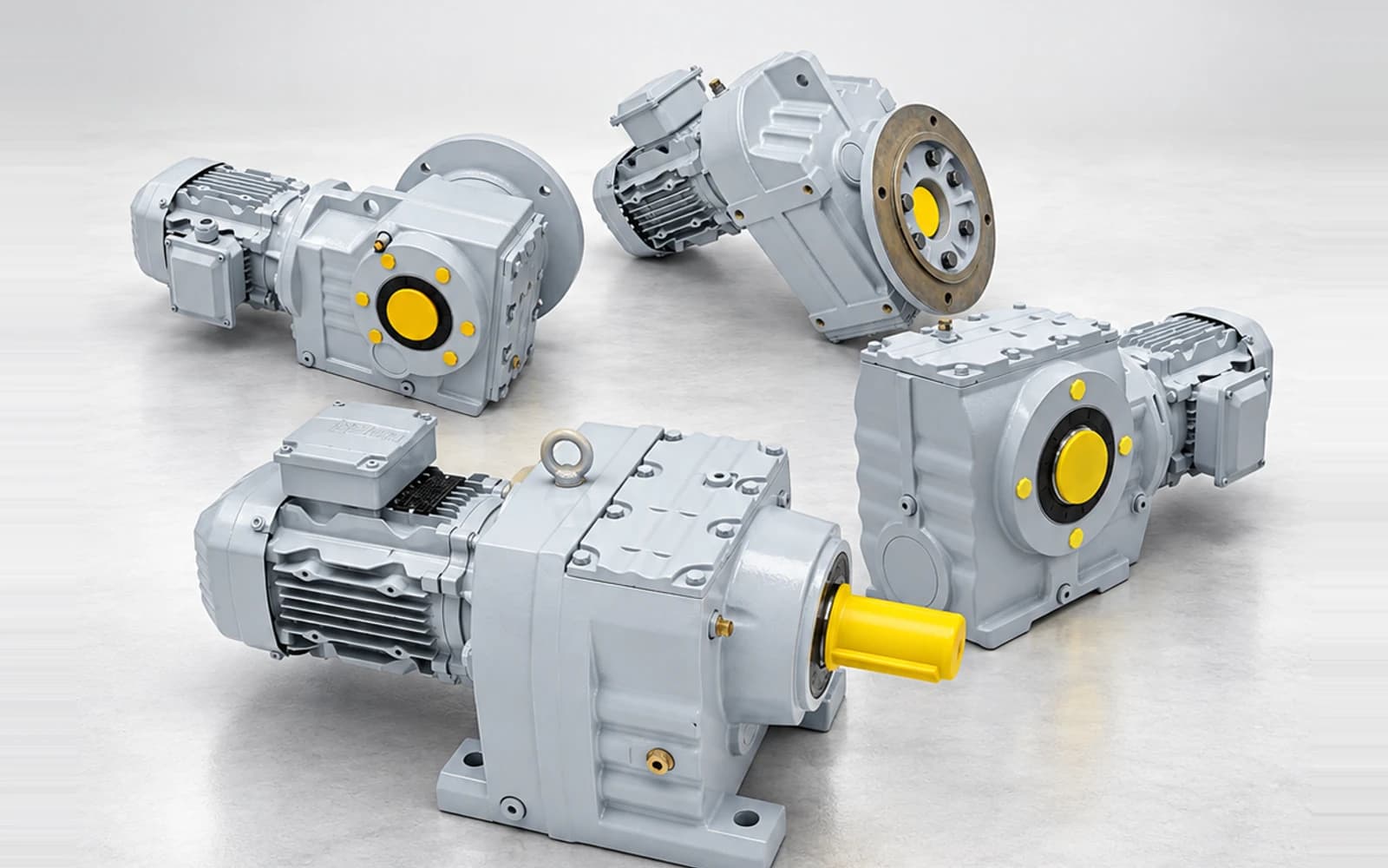
Frequent start-stop and reversing duty is not covered by adding a start count to the power figure you already have. Three independent input groups must each be filled in far enough for the band to be identified: work-machine type with daily loaded running time, starts per hour with daily loaded running time, and ambient temperature where an S series unit is involved. If any group cannot be placed, a supplier can only ask back. That is a hard stop in the workflow, not a courtesy question.
Why a start count on its own cannot be used
A bare "20 starts per hour" cannot enter a selection, because it is missing the other dimension of the same judgement: daily loaded running time.
Twenty starts per hour with one hour of loaded running a day and twenty starts per hour with twenty hours of loaded running a day are not comparable cases. The first unit spends most of its life cooling down; the second has almost no cooling window at all. Starts per hour and loaded running time sit in the same group for exactly this reason — neither carries usable information without the other.
It also explains why selection tables band the two together instead of listing two figures that can be reported independently. If either dimension cannot be placed in a band, the total duty factor cannot be established. That is a hard block in the process, and treating it as a formality is how a wrong model gets onto a purchase order.
The six inputs a selection needs, and the three duty groups behind them
At minimum, six items have to be on the table:
| # | Input | What it fixes | If it is missing |
| 1 | Product series (R/F/K/S, H/B or P) | Which coefficient set and selection table applies | No table to work from |
| 2 | Work-machine type | The base band, including whether the reversing row applies | Only a request back for duty details |
| 3 | Daily loaded running time | The band, jointly with starts per hour | Band cannot be fixed |
| 4 | Starts per hour | The band, jointly with loaded running time | Band cannot be fixed |
| 5 | Running power P (kW) | Torque at the output of the gear reducer | Torque cannot be calculated |
| 6 | Target output speed n2, or the ratio i | Output speed and reduction ratio | No selection possible |
Items 2 to 4 carry the first two of the three duty groups: work-machine type with loaded running time, and starts per hour with loaded running time. The third group is ambient temperature, which applies only where an S series geared motor is specified — R/F/K series do not use it.
One point is worth stating plainly: the duty factor is not a single number. It is built from three components — one from the work-machine type together with daily loaded running time, one from starts per hour together with daily loaded running time, and for the S series one from ambient temperature. A total exists only once every applicable component has been placed in a band, and even a complete total stays a candidate until each participating component has been reviewed. A candidate total is not a commitment.
How the duty is usually reported, and how it has to be reported
This is the most practical part of the page. The same physical situation, written two ways, decides whether a selection can be made at all.
| What is usually written | Problem | What should be written |
| "20 starts per hour" | No loaded time, so the band cannot be fixed | "20 starts per hour, 8 hours loaded per day" |
| "Runs all day" | Continuous and intermittent loading cannot be told apart | "8 hours loaded, 16 hours idle per day" |
| "It reverses" | No reversing frequency, and no word on whether reversal happens under load | "Reverses every 2 minutes, under load" |
| "Heavy duty" | Heavy duty is a conclusion, not an input | Give the work-machine type and the load spectrum |
| A power number only | Not stated whether this is the motor rating or the actual running power | Say whether it is running power or installed power |
| "It needs to run slower" | No selection possible | Give the target output speed n2 or the ratio i |
| "Normal ambient" | The S series needs an actual temperature | Give the maximum ambient temperature |
Band boundaries belong to the reviewed current catalogue and are not restated here. Tables differ between series and between editions, and a boundary copied across from the wrong one is worse than no boundary at all.
Reversing is a separate row in the work-machine classification, not an extra multiplier
Reversing is not an additional factor applied on top of a non-reversing result. It is a separate row in the work-machine classification.
In the duty factor table the same kind of equipment appears more than once: one row for the version without reversing, another row for the version with it. Reversing therefore enters through the class the work machine is placed in. Nothing is multiplied on afterwards, and there is no single reversing coefficient that could be laid over a no-reversing figure. A buyer and a supplier who treat it as a multiplier are not simply disagreeing about the numbers; they are working from different rules.
Two practical consequences follow:
- State at inquiry time whether the drive reverses. Report a start count, leave reversing out, and the machine is classified into the wrong row — the result is then wrong in a way that no later arithmetic repairs.
- Give the reversing frequency together with the load state at the moment of reversal. "Reverses every 2 minutes, under load" and "reverses twice a day, at no load" are different duties, even where the start count per hour is identical.
Referring load inertia to the motor shaft, and the torque it takes to accelerate
In frequent start-stop duty the accelerating and decelerating phases often demand more torque than steady running does. Two inputs are needed to calculate that torque: load inertia and acceleration time.
Refer the load inertia to the motor shaft first:
J_total = J_motor + J_load / i²J_motor is the rotor inertia of the motor, J_load is the load-side inertia referred to the load shaft, i is the ratio of the speed reducer, and the unit throughout is kg·m². The larger the ratio, the smaller the load inertia seen at the motor shaft — it decays with the square of the ratio. That is one practical reason planetary and multi-stage units hold up well in frequent start-stop duty.
Then the angular acceleration:
α = 2π · Δn / (60 · Δt)Δn is the change in speed in rpm, Δt is the acceleration or deceleration time in s, and α comes out in rad/s².
And from those two, the acceleration torque:
T_acc = J_total · αT_acc is in N·m. It has to be added to the steady-state load torque before it means anything: the sum is the instantaneous torque the gearbox has to deliver while the drive accelerates. This is also where the warning sits — if the torque quoted by the supplier covers steady state only, while the acceleration time is squeezed very short, this term is the real bottleneck in the selection. A torque figure silent about the accelerating phase is not evidence that the accelerating phase is safe.
Equivalent thermal load: the quantity that blocks frequent-start selections
Most inquiries watch peak torque and miss the quantity that more often decides the case: heat.
Every start-stop cycle carries an acceleration and a deceleration in which torque sits above the steady-state value. Duty of this kind produces heat faster than continuous running at the same power, and the higher the start frequency, the larger the share of the cycle spent accelerating. Engineering judges the cycle by its equivalent thermal load:
T_rms = √( Σ T_i² · t_i / Σ t_i )T_i is the torque of segment i in N·m, t_i is the duration of segment i in s, and the summation runs over the whole working cycle. Squaring the torque weights the short high peaks, and dividing by total time spreads them back across the cycle, so what comes out describes heating rather than instantaneous shock.
Two checks follow, and both are needed:
- Peak check — the maximum instantaneous torque,
T_accincluded, must not exceed the allowable peak of the selected model. - Thermal check — the cycle-equivalent thermal load must not exceed the allowable continuous output of the selected gear reducer, with ambient temperature and cooling conditions taken into account.
Running the peak check and skipping the thermal check is the most common selection mistake in frequent start-stop duty. The allowable values behind both checks have to be confirmed by the supplier for the specific model and cooling arrangement.
Braking method decides where the energy goes
Reversing and frequent stopping both involve braking, and the braking method determines what the kinetic energy becomes and where the heat appears.
| Braking method | Where the kinetic energy goes | Where the heat appears | What must be stated to the supplier |
| Mechanical braking (spring-applied brake) | Converted to heat by friction | The friction pair of the brake | Permissible braking work of the brake, braking frequency, stopping time |
| Variable-frequency braking (dynamic braking) | Dissipated in the braking resistor | The braking resistor | Braking unit rating, resistor power, duty cycle |
| Regenerative braking | Returned to the DC bus or to the supply | The drive and the regeneration unit | Regenerative capacity, grid conditions, whether regeneration is permitted |
The point to hold on to: where the energy goes is where the heat appears. If most of the braking falls on a mechanical brake, the permissible braking work and the permitted braking frequency are inputs the supplier must confirm for the model — they cannot be assumed by the buyer. Writing the braking task off as "the gearbox will self-lock" is neither valid nor safe: reversing and frequent-stop duty need a braking scheme of their own.
Condition-by-condition judgement
| Duty condition | Main risk | Data still needed | Recommended action |
| High starts per hour with long daily loaded time | Heat accumulation, unit selected too small | Bands for both starts per hour and loaded time | Run the peak and thermal checks together |
| Reversing under load, reversal frequent | Bidirectional shock adds up; classification lands in the wrong row | Reversing frequency, load state at reversal | Mark the reversing row explicitly and give the reversing parameters |
| Acceleration time squeezed very short | Acceleration torque exceeds steady-state torque | Load inertia, acceleration time | Supply the inertia and recheck T_acc |
| High-inertia load (fans, flywheels, long conveyors) | Referred inertia still demands large acceleration torque | J_load and the ratio | Refer through J_total = J_motor + J_load / i², then recheck |
| Braking duty falling on the mechanical brake | Brake overheating, fast wear of the friction pair | Braking work, braking frequency, stopping time | Supplier confirms permissible brake values for the model |
| High ambient temperature (S series especially) | The thermal check basis shifts | Maximum ambient temperature, cooling method | Supply the ambient value and recalculate on a thermal balance |
| Load direction includes radial or axial components | Bearings loaded beyond the allowable | Magnitude, point of application, overhung distance | No availability commitment before the dimensions are reviewed |
Site checklist
Observable while running
- The actual share of loaded versus idle time within one complete working cycle.
- Actual starts per hour — read it from a counter, do not estimate it.
- Whether reversal happens under load, and whether there is noise or impact at reversal.
- Whether motor current during acceleration is clearly above the steady-state level.
Requires shutdown
- Record the motor nameplate and the actual running power, keeping installed power and running power apart.
- Measure or obtain the load-side moment of inertia; where no figure exists, give the geometry and mass of the load so that it can be estimated.
- Record the acceleration time — the actual time from command to reaching the target speed.
- Confirm the brake type, the braking frequency and the actual stopping time.
- Confirm the maximum ambient temperature and the cooling method (natural, fan, forced ventilation).
Must be handled by qualified personnel
- The final judgement on the peak and thermal checks, and confirmation of the permissible braking work of the brake.
- Review of the braking and fall-arrest design wherever personnel safety is involved — self-locking of the gearbox is not a substitute.
Common mistakes and where this article stops
Common mistakes
- Reporting starts per hour without the daily loaded running time.
- Treating "it reverses" as a remark, with no reversing frequency and no load state at reversal.
- Assuming reversing needs a multiplier on the factor — it is a separate classification row within the work-machine type.
- Running the peak torque check and stopping there, with no thermal check.
- Using installed power in place of the actual running power.
- Not knowing the load inertia, and not supplying the geometry and mass from which it could be estimated.
- Leaving the braking task to "the gearbox self-locking", or assuming a brake can brake an unlimited number of times.
Where this stops
- The input list, the classification logic and the formulas here apply to frequent start-stop and reversing duty on R/F/K/S modular geared motors, H/B industrial gearboxes and P series planetary gearboxes.
- No duty factor value, no start-per-hour limit, no inertia limit and no braking-frequency limit are given, and no band boundary is restated. Those come from the reviewed current catalogue and from engineering confirmation.
- The formulas state variable relationships and units only. They must be rechecked against actual duty data before they are used to support a selection conclusion.
- This article does not replace a functional safety design for a specific machine.
Data checklist to send a supplier
| # | Data item | Note |
| 1 | Product series | R/F/K/S, H/B or P |
| 2 | Work-machine type | As specific as possible; state whether it falls into a reversing category |
| 3 | Daily loaded running time | In hours, including the share of idle time |
| 4 | Starts per hour | A measured value, not an estimate |
| 5 | Running power P | kW; running power distinguished from installed power |
| 6 | Target output speed n2 or ratio i | Either one is enough |
| 7 | Ambient temperature | Mandatory for the S series, advisable for the others |
| 8 | Whether reversing is required | If so, add the reversing frequency and the load state at reversal |
| 9 | Braking method and stopping time | Mechanical, variable-frequency or regenerative, with the stopping time |
| 10 | Load inertia and acceleration time | Without an inertia figure, give the load geometry and mass |
| 11 | Mounting method and shaft load | Radial and axial loads, overhung distance where present |
About this article and the publisher
This article was written by the technical team of Chengfa Reducer (Changzhou) Co., Ltd. (CHINFAR) and released after technical review. The H/B series industrial gearboxes and P series planetary gearboxes referred to above are supplied by Chengfa Reducer (Changzhou) Co., Ltd., and products are delivered through the joint manufacturing system shared with HUIGUANG.
Related products and technical material:
- R/F/K/S modular geared motors
- H/B series industrial gearboxes
- P series planetary gearboxes
- How service factor affects gearbox selection
Next step
Send the eleven items above to sales@chinfar.com. If one of them is not available yet, say that it is not available instead of putting in an estimate — a missing item can be asked back and filled in, while a wrong estimate puts the classification straight into the wrong row. Selection conclusions are subject to engineering review; this article does not replace a selection calculation for a specific duty.