 ®

Technical guide
Gearbox Backlash Measurement: How to Define, Measure and Specify It
Author: CHINFAR Technical Team · Reviewer: Tinyuen (CHINFAR) · Updated: 2026-11-04
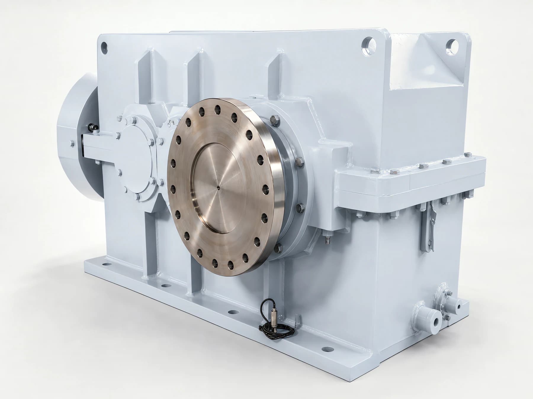
Backlash is the free rotation between the working and the non-working flank of an assembled gear pair. As a purchasing requirement it only works when three things travel together: where it is measured (input shaft or output shaft), the gear ratio, and the unit (arcmin, °, or mm at the pitch circle). A request saying only "low backlash", or a bare number with no position attached, can neither be verified at goods-in nor accepted on site. The rest of this article defines the parameter, converts between its three expressions, explains the measurement, and shows how to write it into a selection sheet and an inquiry.
Backlash is treated here as a single parameter, nothing else. Service factor, mounting position and the general selection input list each have their own article and are not repeated.
Three expressions of one quantity — and why they are not interchangeable
One gear pair can have its clearance described three ways, and conflating the three is the most common failure in technical correspondence between buyer and maker.
| Expression | Symbol | Unit | Where measured | Typical use | Conversion relation |
| Circular backlash | j_t | mm | At the pitch circle, along the tangential direction | Drawing callouts, manufacturing acceptance | j_t = r · θ, with θ in radians and r the radius of the circle on which the measurement is taken |
| Normal backlash | j_n | mm | Normal to the tooth flank | Corresponds to tooth thickness deviation | Spur gear j_n = j_t; helical gear j_n = j_t · cos β_b, where β_b is the base helix angle |
| Angular backlash | θ | arcmin or ° | At a defined shaft end, input or output | Positioning, indexing, reversing drives | θ_out = θ_in ÷ i, with i the gear ratio |
Three points have to be said out loud:
- Spur and helical gears do not share one conversion. On a spur gear the helix angle is zero, so normal and circular backlash are numerically equal. On a helical gear the normal backlash is smaller than the circular backlash and has to be converted through the base helix angle.
- Angular backlash without a shaft end means nothing. On the same gearbox, the angle measured at the input and the angle measured at the output differ by the ratio.
- Circular backlash without a radius means nothing either. The same linear clearance, referred to a larger pitch radius, converts to a smaller angular backlash.
The terminology used here follows the gear-fit system described in DIN 3967, which covers backlash together with tooth thickness deviation and tooth thickness tolerance fundamentals, and the accuracy-grade system for cylindrical gears described in GB/T 10095.1-2008 and ISO 1328-1, which set out definitions and permissible values for deviations on the same tooth flank. Those references identify where the vocabulary and the grading system come from. They are not a statement that any product is certified, conforms to, or has been tested against these standards, and nothing on this page should be read as a conformity claim.
Where the number is taken: input shaft, output shaft, one pair, complete unit
The measurement position decides whether a figure can be accepted directly at goods-in. A gear reducer quoted at the input shaft and the same unit quoted at the output shaft are two different requirements, even when the underlying hardware is identical.
| Measurement position | Quantity obtained | Conversion to output | Where it applies | Caution |
| Input shaft end | θ_in | θ_out = θ_in ÷ i | Small geared motors that are easy to turn by hand | With a large ratio the input angle is magnified, so the output-side deviation is easily underestimated |
| Output shaft end | θ_out | None required | High ratios, heavy loads, positioning duty | Needs enough torque to turn the shaft; record the direction and magnitude of the applied torque |
| A single gear pair | j_t, or the angular backlash of that stage | Converted at the radius of that stage | Drawing acceptance, component-level inspection | Excludes bearing clearance and connection clearances |
| Complete assembled unit | θ_total | — | Inquiry, factory acceptance, on-site re-check | Includes every stage, bearings, key or spline joints and coupling clearance |
For a multi-stage train, total backlash is not the figure of any one stage. It is accumulated with each stage divided by the ratio ahead of it:
θ_total ≈ θ₁ + θ₂ / i₁ + θ₃ / (i₁ · i₂)Here θ₁, θ₂ and θ₃ are the backlash of each stage counted from the input end, and i₁ and i₂ are the ratios of the respective stages. The more stages a unit has and the larger the downstream ratios, the smaller the share a later stage contributes to the total. The first stage, by contrast, enters almost at face value — which is exactly why the input stage deserves separate attention when the backlash allowance is tight.
A complete speed reducer is built from four converted contributions: the backlash of each gear pair, bearing clearance, key or spline connection clearance, and coupling clearance. Leave any one of them out and the whole-unit figure is understated.
Measurement conditions and method classes
A clearance figure is comparable only when the conditions match. Record all of the following with every reading:
- Load: no load.
- Temperature: either the specified ambient temperature or the specified working oil temperature — never a mix of the two.
- Fastening: feet, flange and torque arm tightened to the installation requirement.
- Lubrication: dry, greased or oil-filled, stated explicitly.
- Applied torque: record the point of application, the direction and the magnitude. Too little torque leaves the clearance unseated; too much introduces elastic deflection.
Two method classes cover most shop-floor and site work:
- Hold one shaft, rotate the other. Lock one shaft completely, apply the specified small torque to the other, seat it against the working flank and zero the instrument, then reverse to seat it against the non-working flank and read the difference on a dial indicator or an angle encoder. The advantage is that the complete assembled unit is measured as built, without stripping it down.
- Lead-wire method. Lay soft metal wire between the teeth, roll the pair through mesh, recover the wire and measure the thickness at the crushed section; that thickness is the normal backlash at that tooth position. No special fixture is needed, but the result describes one local position only.
Both methods hold only for the tooth pair and the angular position actually tested. Backlash varies around the circumference, so a single reading does not represent a full revolution: repeat the measurement at several positions spaced evenly around the circle and record both the minimum and the maximum.
Engineering judgement: when the figure needs an extra check
| Condition | Main risk | Additional data needed | Recommended action |
| Bidirectional positioning or frequent reversing | The reversal dead band feeds straight into positioning error and into workpiece surface quality | Allowable lost motion, measurement position, gear ratio | Agree the acceptance basis at the output shaft, in angular backlash |
| Multi-stage train, two stages or more | A single-stage figure is substituted for the whole unit and flatters the result | Ratio of each stage and backlash of each stage | Convert and accumulate by ratio before checking the total |
| High working temperature or a wide temperature swing | The cold-assembly clearance and the hot running clearance are not the same | Gear and housing materials, working temperature, assembly temperature | State the measurement temperature and assess the direction of thermal change separately |
| Drive train includes a coupling, spline or keyed joint | Clearance in the connection is ignored | Connection type, fit tolerance, assembly method | Convert connection clearance into the total |
| Worm and wheel drives | Backlash is mistaken for a self-locking or anti-fall safeguard | Lead angle, friction condition, lubrication method | Complete the brake and fall-arrest design separately; never let backlash stand in for it |
| A gear reducer already in service has to be re-measured | Wear enlarges backlash, so the reading cannot be compared with the factory value | Factory record, running hours, maintenance record | Establish a baseline and compare trends instead of judging a single reading |
On-site inspection checklist
Observable while running
- Whether there is a visible pause or impact on reversal — record the direction and the load at the time.
- Whether positioning repeatability degrades as the unit warms up.
- Whether the output end shows abnormal end float or periodic noise.
Requires shutdown
- Hold one shaft and turn the other by hand in both directions, then confirm whether the reading matches the factory record.
- Check that feet and flange fasteners are properly tightened — an untightened unit reads high and cannot be used as a basis for judgement.
- Check that clearance at the key, spline, shrink disc or coupling is inside the measurement boundary.
- Record ambient temperature and oil temperature, and confirm the conditions are comparable with the previous measurement.
Must be handled by qualified personnel
- Deciding whether wear has passed the limit and whether the gear pair needs replacement or adjustment.
- Where braking, fall arrest or personnel safety is involved, a backlash conclusion never substitutes for a safety design review.
- Re-measurement and acceptance of backlash after strip-down and re-assembly.
Common mistakes and where this article stops
Common mistakes
- Quoting a single number with no measurement position and no ratio attached.
- Passing an input-shaft angular figure off as the output figure — with a large ratio the two are separated by the ratio itself.
- Substituting the backlash of one gear pair for the whole-unit figure and ignoring bearing clearance and connection clearance.
- Treating backlash as equal to positioning accuracy or repeatability. It is one contributing factor; control-system compensation, structural stiffness and load also shape the final positioning result.
- Treating backlash as a guarantee of self-locking or fall arrest. Self-locking depends on lead angle, friction and lubrication and is unrelated to the backlash figure.
- Comparing two sets of readings taken at different temperatures or with fasteners in different states.
Where this stops
- The definitions, conversions and measurement methods here apply to the gear pairs and complete units of general industrial gearboxes, planetary gearboxes and geared motors.
- No specific backlash value, tolerance band, or accuracy-grade-to-backlash value is given anywhere in this article. Such figures have to be established from the drawing and manufacturing tolerance of the specific model.
- Standard references here identify the origin of the terminology and the grading system only. They do not mean that any product is certified, compliant with, or tested to those standards.
Writing backlash into a selection requirement and an inquiry
An executable wording has four parts:
Backlash requirement: angular backlash at the output shaft end shall not exceed ____ arcmin, measured at no load, at an ambient temperature of ____ °C, with feet and flange tightened to the installation requirement; gear ratio i = ____; method: lock the input shaft, apply the specified torque to the output shaft in both directions and read the dial indicator difference; measure the same unit at ____ positions evenly spaced around the circumference and record the maximum.
Each part corresponds to an action somebody can verify. Drop any one of them and the two sides may still disagree about what "pass" means.
If the allowable lost motion is not yet known, do not fill the blank with an impression. The safer route is to hand the duty over to the supplier: state the application, the positioning requirement, the acceptable reversal dead band, the load direction and the running temperature, and let engineering return a backlash range that is achievable for the model and its manufacturing tolerance — then write that into the technical agreement.
Data checklist to send a supplier
| # | Data item | Note |
| 1 | Gear ratio i | Must match the actual configuration; for a multi-stage unit give the ratio of each stage |
| 2 | Measurement position | Input shaft / output shaft / single gear pair / complete unit |
| 3 | Unit and expression | arcmin, °, mm at the pitch circle (j_t) or mm normal (j_n) |
| 4 | Allowable backlash | One-directional or bidirectional, and whether connection clearance is included |
| 5 | Load direction and maximum working load | Establishes the usable clearance remaining on the loaded flank |
| 6 | Positioning and repeatability requirement | Backlash is only one influencing factor, so state the requirement alongside it |
| 7 | Working temperature range and assembly temperature | Used to assess the direction of thermal change in the running clearance |
| 8 | Mounting method and fastening condition | Foot-mounted, flange-mounted, torque arm or shaft-mounted |
| 9 | Existing nameplate, drawing or measurements from the old unit | Mandatory for replacement and retrofit work |
About this article and the publisher
This article was written by the CHINFAR Technical Team and released after technical review. The H/B series industrial gearboxes and P series planetary gearboxes referred to above are supplied by Chengfa Reducer (Changzhou) Co., Ltd., and products are delivered through the joint manufacturing system shared with HUIGUANG.
Related products and technical material:
- H/B series industrial gearboxes
- P series planetary gearboxes
- What data a gearbox inquiry needs
- Contact the CHINFAR technical team
Next step
Send the ratio, the measurement position, the allowable backlash together with its unit, the load direction, the mounting method, and any nameplate data or measurements from the old unit to sales@chinfar.com. On that basis we will confirm the backlash basis and the acceptance method that are achievable for the configuration. Selection conclusions are subject to engineering review; this article does not replace a selection calculation for a specific duty.