 ®

Technical guide
Brake Geared Motor Selection: What Separates a Stopping Brake from a Holding Brake
Author: CHINFAR Technical Team · Reviewer: Tinyuen (CHINFAR) · Updated: 2026-11-04
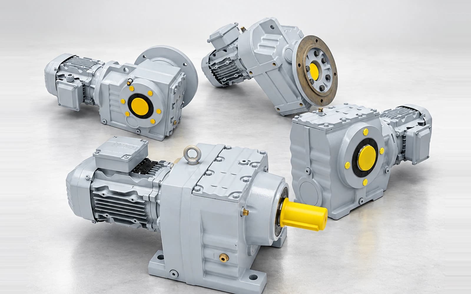
Brake geared motor selection turns on a distinction that is not about strength. A stopping brake brings a moving system to rest, and its governing quantity is braking energy per stop multiplied by stops per hour — a thermal constraint. A holding brake holds a load that is already stationary, and its governing quantity is static holding torque — a constraint on force. In normal running a holding brake dissipates almost nothing.
Mixing the two up is costly in both directions. A holding brake pressed into stopping duty destroys its friction pair within a short number of stops. A stopping brake used only to hold adds cost, bulk and wear, and does not reliably buy static dependability in return.
One question tells the two apart
Before any figure is written down, one question settles the classification:
Does this brake act while the system is still moving, or only once it has already come to rest?
- It acts while the system is moving — a stopping brake, also called a service brake. Size it on braking energy and stops per hour.
- It acts only after the load has stopped — a holding brake. Size it on static holding torque.
- It does both — a mixed duty, and both checks apply (see Section 5).
The question works because the two jobs consume different things. One consumes energy; the other only maintains a force. Nothing in the answer turns on the brake being stronger or weaker.
The two jobs side by side
| Dimension | Stopping brake | Holding brake |
| Task | Decelerate a moving system and bring it to rest | Maintain position while the system is at rest |
| Main energy | System kinetic energy, including any change in potential energy | None passes through the friction pair in normal running |
| Governing quantity | Braking energy per stop, plus stops per hour | Static holding torque |
| Type of constraint | Thermal | Force (torque) |
| Wear | Every stop wears the friction pair | Wear happens mainly at power loss and emergency stops |
| Failure behaviour | Usually built fail-safe as well | Must be fail-safe — it applies when the supply is lost |
| Typical applications | Frequent starting and stopping, positioning, fast stops | Hovering vertical loads, holding position on power loss, maintenance locking |
The two right-hand columns are not two settings of one parameter. Every row follows from the single difference above: whether the brake has to absorb energy, or only resist a load.
Stopping brake: where the energy comes from, and how the heat is accounted for
Stopping duty is a heat problem before it is a torque problem. Kinetic energy has to be turned into heat, and that heat has to leave the friction pair as fast as it arrives.
Start with the angular velocity:
ω = 2π · n / 60n is the speed in rpm and ω is the angular velocity in rad/s. The kinetic energy of the system is:
E_k = ½ · J_total · ω²J_total is the total inertia referred to the brake shaft, in kg·m². Total is the operative word: motor rotor, gear unit, coupling and load, all referred to the same shaft.
Holding the system to a given stopping time takes this braking torque:
T_b = J_total · ω / t_bt_b is the stopping time in s and T_b comes out in N·m. That expression leaves load torque out, and the omission matters, because the direction of the load torque decides whether it helps or fights the brake:
- Lowering a weight, the load torque drives the motion, so the brake has to overcome it as well as the inertia, and the braking torque required is larger.
- Hoisting, or running horizontally, the load torque opposes motion, so the braking torque required is smaller.
Calculating from J_total alone, with no thought for the direction of the load torque, is where lowering duty most often goes wrong.
Under a uniform deceleration, the angle turned during the stop is:
θ_b = ω · t_b / 2and the energy taken out per stop is:
W_b = T_b · θ_bW_b is in J. Multiply by the stops per hour and the quantity the thermal check needs appears:
W_h = W_b · NN is stops per hour and W_h comes out in J/h.
Heat is the criterion that limits a stopping brake
The heat rejection capacity of the brake must be at least `W_h`.
Heat that cannot leave accumulates. The friction pair runs hotter with each successive stop, and as it heats up, braking torque falls while wear accelerates — each effect drives the other. This is why the governing quantity in stopping duty is not "is the torque high enough" but "can the heat get out".
It is also why the same brake is unremarkable at one stop an hour and a problem at dozens. The force demanded of it hardly changes; the energy it has to shed per hour does. The difference is not in the force, it is in the heat.
Holding brake: the only requirement is that it holds
The logic here is different in kind. The system is already at rest, and the brake's task is to keep it there.
While the machine runs normally the friction pair does not move and dissipates nothing; wear falls at the moments when the brake acts — a power loss, an emergency stop. The governing quantity is therefore static holding torque: whether there is enough of it to hold the load, and whether it will slip while holding.
Three points:
- Fail-safe is the default form. Spring-applied, released electrically: the brake applies when the supply is lost. That is what the holding task asks for. Built the other way round — applied electrically — a supply failure removes the holding force, which on a vertical load is not an acceptable design.
- The holding margin comes from the applicable requirement, not from habit. Holding torque does not have to merely equal the load; a margin is needed, and how large that margin must be is set by the functional safety requirement and the applicable standard. No margin value is given here.
- Slipping is more dangerous than wearing. A holding brake that slips slightly for long periods heats its friction pair slowly and degrades it gradually, and a failure of that kind is hard to notice before it matters.
Mixed duty: most machines use both, one after the other
Few machines are purely stopping or purely holding. Most run a two-stage cycle:
Accelerate → run at speed → decelerate (stopping brake) → standstill → hold with the supply off (holding brake) → release → accelerate again.
On such a machine the same brake does both jobs in turn: it absorbs energy, then holds for a long period. Selection therefore has to satisfy the thermal criterion and the static holding requirement at the same time; meeting one of them is not a selection.
Order of judgement:
- Calculate
W_hand check the thermal criterion. - Calculate the static holding torque and check the force requirement.
- Only when both hold is there anything worth discussing about a model.
Doing the force check first is a common ordering error. Force is easy to satisfy; the thermal limit is the one that only shows itself after a long run of stops.
Safety boundary: a brake is not automatically a safety function
This is the one part of the subject that cannot be left vague.
A brake does not in itself constitute a safety function. That it can stop a load does not mean it has been designed, verified and rated to a functional safety requirement. Where any of the following applies, a functional safety design and verification has to be carried out separately:
- suspended loads — vertical hoists, lifting platforms;
- a no-fall-on-power-loss requirement;
- maintenance locking where a person works beneath the equipment;
- any position in which a brake failure would injure a person.
Two further boundaries are as important:
- Gearbox self-locking is not a substitute for a brake. Self-locking depends on lead angle, friction and lubrication state. It is a property of an operating condition, not a dependable safety device.
- A manual release has to be confirmed separately. Maintenance with the supply off means releasing the brake by hand; state at selection time whether a manual release is needed, and how it is reset.
This article does not replace functional safety design and verification.
Condition-by-condition judgement
| Duty condition | Main risk | Data still needed | Recommended action |
| Horizontal running, frequent starting and positioning | Heat accumulation, falling braking torque | Total inertia, stopping time, stops per hour | Calculate W_h and run the thermal check first |
| Vertical hoisting that has to hold on power loss | Fall; this is a safety function | Load, static holding torque requirement, safety level | Design to a functional safety requirement, not to a brake catalogue alone |
| Lowering a weight | Load drives the motion, braking torque insufficient | Magnitude and direction of the load torque | Size for the driving-load case, with the larger braking torque |
| Long holding after a stop | Slight slip, gradual failure | Holding duration, whether fail-safe is required | Fix the fail-safe form and the source of the holding margin |
| Moving duty and long holding in one machine | Only one of the two is satisfied | Both W_h and the static holding torque figures | Check both; do not trade one for the other |
| Maintenance with the supply off requires manual release | Brake cannot be released, or releases by mistake | Whether a manual release is needed, how it is reset | Specify the manual release explicitly |
| A person working beneath the equipment | Brake failure injures a person | Required functional safety level | Independent safety design; the brake does not carry it alone |
| High ambient temperature or heavy dust | Poorer heat rejection, contaminated friction pair | Ambient conditions, required ingress protection | Correct the thermal criterion for the environment |
Site checklist
Observable while running
- Whether the brake area runs noticeably hotter after each stop, and whether the temperature climbs stop after stop.
- Whether braking distance and stopping time grow with service life — an early sign of friction-pair wear.
- Whether there is unusual noise from the brake, drag, or incomplete release.
- Whether a vertical load creeps down slowly once it has been stopped.
Requires shutdown
- Confirm the brake type and form: fail-safe (applies on power loss) or electrically applied.
- Confirm whether the duty is stopping, holding, or the two-stage mixed cycle.
- Record the actual stops per hour and the stopping time of each.
- Check the friction-pair wear against the permitted range, per the manufacturer's maintenance manual.
- Confirm whether a manual release is needed, and how it is reset.
Must be handled by qualified personnel
- The final check of the thermal criterion and of the static holding torque.
- Completion of the functional safety design and verification wherever personnel safety, a suspended load or a no-fall requirement is involved.
Common mistakes and where this article stops
Common mistakes
- Using a holding brake as a stopping brake. The most typical and the most expensive error: heat input far beyond the design, and the friction pair is finished within a short service period.
- Using a stopping brake as a holding brake. Unnecessary bulk and cost, and static slip behaviour that is not necessarily better than a brake designed to hold.
- Calculating braking torque only, never the braking energy per hour, and so ignoring the thermal constraint.
- Sizing a lowering application on the torque of a horizontal one, with no allowance for the load driving the motion.
- Assuming that a brake which can stop the load is therefore safe, without separating the functional safety requirement.
- Substituting gearbox self-locking for a braking scheme.
- Not deciding at selection time whether a manual release is needed, and finding at maintenance that the brake cannot be released.
Where this stops
- The comparison and the formulas here apply to the classification of the braking task and to preliminary calculation on R/F/K/S series brake geared motors.
- No brake values are given in this article: rated braking torque, permissible braking work, permitted braking frequency, brake response time, holding-torque margin, model codes and mounting dimensions are all excluded. These have to be confirmed by the supplier for the specific model against the current catalogue.
- Braking work and the thermal criterion as set out here are an engineering estimate; an actual selection has to be checked against the braking-work versus frequency curve supplied by the manufacturer.
- This article does not replace functional safety design and verification.
Data checklist for a brake geared motor enquiry
| # | Data item | Note |
| 1 | Total inertia referred to the brake shaft | Motor rotor, gear unit, coupling and load, all referred to the same shaft |
| 2 | Stopping time required | From the braking command to a complete standstill |
| 3 | Stops per hour | Measured, or set by the process — not an estimate |
| 4 | Load direction | Horizontal, vertical hoisting, vertical lowering |
| 5 | Magnitude and direction of the load torque | Decides whether the load drives or resists |
| 6 | Whether the position must be held on power loss | If so, add the holding duration and the safety level |
| 7 | Whether a manual release is required | If so, state how it has to be reset |
| 8 | Braking task type | Stopping, holding, or the two-stage mixed cycle |
| 9 | Ambient temperature and dust | Affects heat rejection and friction-pair contamination |
| 10 | Mounting method and space available | Affects the choice of brake envelope |
| 11 | Applicable safety requirements | A required functional safety level, or personnel working beneath the equipment |
Item 8 is the one most often skipped: many enquiries say only that the drive "needs a brake", without saying whether the brake is used while the machine is moving or after it has stopped. Left unanswered, the other ten items can all be calculated and still land in the wrong place.
About this article and the publisher
This article was written by the technical team of Chengfa Reducer (Changzhou) Co., Ltd. (CHINFAR) and released after technical review. The R/F/K/S modular geared motors referred to above are supplied by Chengfa Reducer (Changzhou) Co., Ltd., and products are delivered through the joint manufacturing system shared with HUIGUANG.
Related products and technical material:
- R/F/K/S modular geared motors with integrated brakes
- What data a gearbox enquiry needs: the selection input checklist
- Talk to the CHINFAR technical team
Data preparation for frequent start-stop duty is covered in its own article, What Data a Gearbox Selection Needs for Frequent Start-Stop and Reversing Duty, and is not repeated here.
Next step
Send the eleven items above to sales@chinfar.com. If you need only one judgement from this page, answer item 8 first — does the brake act while the machine is moving, or only after it has stopped? That answer decides whether the case is calculated on heat or on force. Selection conclusions are subject to engineering review; where personnel safety is involved, a separate functional safety design and verification has to be completed.