 ®

Technical guide
Can an NMRV Worm Gearbox Self-Lock?
Author: CHINFAR Technical Team · Reviewer: Tinyuen (CHINFAR) · Updated: 2026-11-04
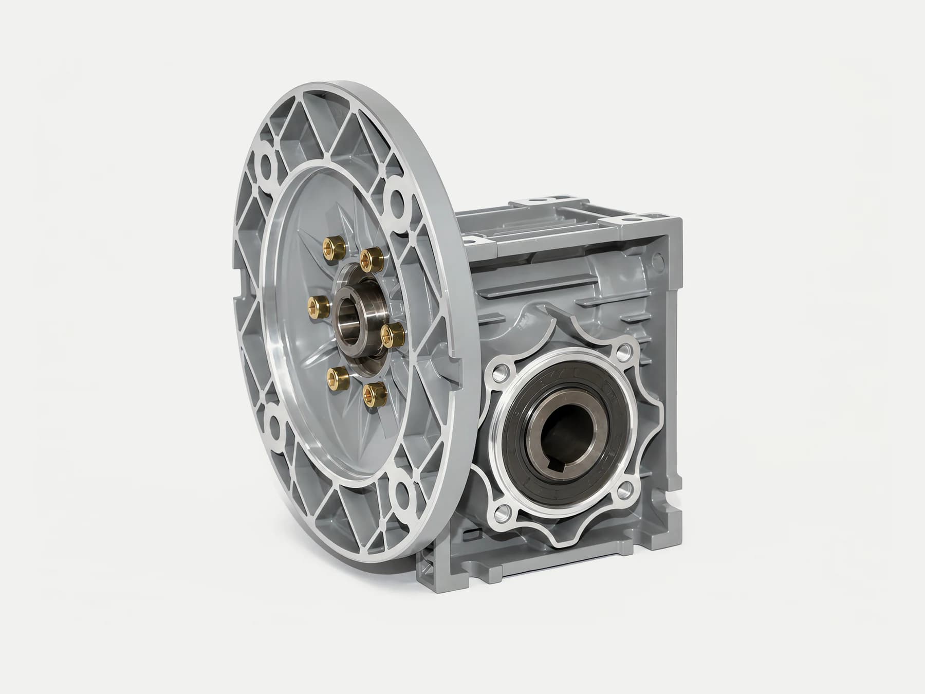
No — and above all, not as a safety brake. An NMRV worm gearbox does carry a self-locking tendency, but a tendency is not a brake. Whether the tendency holds depends on the lead angle, the friction state, lubrication, vibration and load direction and size — all of which move while the unit runs. Self-locking is "may hold under some conditions". A safety requirement is "must hold under all conditions". A probability cannot stand in for a certainty.
The verdict, in six rows
| Question | Answer |
| Does an NMRV have a self-locking tendency? | Yes. It is strongest on a single-start worm |
| Can that tendency be relied on? | No |
| What is the criterion? | Lead angle λ ≤ friction angle ρ |
| Once the criterion is met, is the unit locked for good? | No. The friction angle drifts with lubrication, wear and temperature |
| Can self-locking stand in for a brake? | No |
| Lifting, suspended loads, someone possibly underneath — is self-locking the anti-fall device? | Never. Independent braking, travel limits and a safety device are required |
Why it self-locks: λ against ρ
The self-locking condition of a worm drive is a single inequality:
λ ≤ ρλ is the lead angle and ρ is the friction angle. The friction angle follows from the coefficient of friction:
ρ = arctan(μ)μ is the coefficient of friction, and both ρ and the result of arctan are angles.
Read plainly, the pair says this: the worm can only resist being back-driven while the lead angle is small enough not to exceed the friction angle. Let the lead angle exceed the friction angle and back-driving becomes possible.
The lead angle itself is set by geometry:
tan λ = z₁ / qz₁ is the number of starts on the worm — its thread count — and q is the diameter quotient.
Two consequences follow at once, and both are the reason this page exists. First, z₁ sits in the numerator: more starts means a larger lead angle, and a harder time satisfying λ ≤ ρ. Second, ρ is not a constant of the drawing. It is read off μ, and μ is a property of the contact as it actually is at that moment, not as it was when the unit was specified.
The number of starts decides the tendency
From tan λ = z₁ / q it follows directly that the more starts, the larger the lead angle, and the harder it is to satisfy `λ ≤ ρ`.
| Starts | Lead angle | Self-locking tendency | Efficiency tendency |
| Single-start | Small | Relatively strong | Relatively low |
| Double-start | Medium | Relatively weak | Medium |
| Three-start and above | Large | Very weak, or none | Relatively high |
That table also explains where a common misconception comes from: someone takes the experience of a single-start unit and generalises it to every NMRV. Double- and three-start units are designed toward efficiency, not toward self-locking. Treating them as self-locking is an error of direction, not a matter of degree.
Self-locking and efficiency exclude each other
The efficiency of a worm drive is written approximately as:
η = tan λ / tan(λ + ρ)η is the efficiency.
This expression states something very practical: the smaller `λ` is, the lower the efficiency. And self-locking requires a small λ. Therefore:
Self-locking and high efficiency conflict geometrically. To get self-locking you accept low efficiency; to get high efficiency you necessarily weaken the self-locking tendency.
Which means the requirement "a worm gearbox that is both efficient and reliably self-locking" does not stand up as a requirement at all. If self-locking is genuinely designed in, the price is heat and energy consumption. If efficiency comes first, then self-locking is the less dependable of the two.
This exclusion is the physical root of "self-locking cannot be a safety function". A safety function should not be built on a parameter that fights efficiency directly, and is therefore always the first thing squeezed when design pressures arrive.
Six conditions that break it
Even where λ ≤ ρ is satisfied at the factory, the following six conditions defeat it.
| Condition | Why self-locking fails | Direction of change |
| Lubrication state | With full lubrication μ is low and so is ρ, which makes λ > ρ easier to reach. With starved lubrication μ rises and the unit locks more readily — but a dry contact cannot be relied on | Changes continuously in service |
| Vibration | Vibration lifts the contact surfaces apart for an instant, static friction is broken, and a mechanism that should have held slips | Common on site |
| Load direction and size | The more the load assists rotation, and the larger it is, the more easily the back-driving torque overcomes friction. Lowering loads break through first | Follows the duty |
| Wear | Wear on the gear flanks changes the contact and its friction behaviour, so μ drifts | Accumulates with time |
| Temperature | Oil temperature changes the film and the viscosity, and μ moves with them | Follows operation and season |
| Number of starts (a design variable) | More starts means a larger λ and a harder time with λ ≤ ρ | Settled at the selection stage |
Note that the first five are things that change while the unit runs. That is why "this one holds" can only ever mean "it holds at this moment, in this state", and never "it holds".
The lubrication row deserves a second look, because it is counter-intuitive: when lubrication gets worse, the self-locking tendency gets stronger, because friction rises. That is not good news. It means the contact is running in dry or boundary lubrication, and wear and temperature rise will follow. "It locks because the oil is bad" is a dangerous coincidence, not a design basis.
Scenario by scenario
| Use case | Can self-locking be relied on? | What to do instead |
| Horizontal conveyor, back-driving not possible | Usable as a running characteristic for reference | Select normally; self-locking is not treated as a function |
| Power loss only needs a slow run-down, no fall risk | Not advisable | A failsafe brake, to reach a controlled stop |
| Vertical lifting, must not drop when the power is cut | Never | Failsafe brake + travel limit + safety device, verified by the machine builder |
| Suspended load, a person may be standing underneath | Never | An independent safety brake system, designed and verified to the applicable functional safety requirements |
| Sloped or inclined mounting, the load has a downhill component | Never | An independent brake, with the downhill torque calculated |
| Maintenance lock-out | No | A mechanical locking device that does not depend on the transmission |
| Vibration or shock environment | No | An independent brake plus positive locking; self-locking is not a basis |
In one line: only where braking was never needed is self-locking harmless; wherever braking is genuinely needed, self-locking is not enough.
The safety boundary
This is the one section of this page that leaves no room for interpretation.
- Self-locking must not be taken as a guarantee of personnel safety braking. It is a running characteristic that may hold. It is not a verified safety function.
- Equipment involving lifting, suspended loads, people or fall risk must have independent braking, travel limits and a safety device, verified by the machine builder. What the supplier provides is the transmission component. Whether a safety function holds is decided by the design of the complete machine.
- Where holding position after power loss is required, use a failsafe brake — one that applies when the power is cut and releases only when energised. Do not depend on self-locking.
- Do not substitute self-locking for a braking scheme. Self-locking and braking are two different things: the first is a by-product of geometry and friction, the second is a purpose-designed, controllable function.
None of this is a manufacturer's disclaimer. It follows from the physics of a transmission component: any property that depends on friction conditions holding is not sufficient to carry a safety function.
Condition-by-condition judgment table
| Item to judge | If met | If not met | Data needed |
| Is the worm single-start? | The self-locking tendency is comparatively strong | With multiple starts, self-locking should not be expected | Model and ratio |
| Is lubrication in its normal state? | The coefficient of friction is within the design expectation | Self-locking "appears to hold", but on abnormal friction | Oil type, oil change records |
| Is there continuous vibration? | Static friction may be repeatedly broken | The condition is comparatively stable | Site vibration |
| Does the load have a downhill component? | The back-driving torque is large | Back-driving is unlikely | Mounting angle, load direction |
| Is holding position after power loss required? | A failsafe brake is mandatory | The stopping method still has to be assessed | Process and safety requirements |
| Could a person be underneath the equipment? | Design to functional safety is mandatory | Basic guarding is still required | How the site is worked |
| How long has the unit been running? | Accumulated wear may have changed the friction behaviour | Close to as-built condition | Running hours |
| Has it ever slipped or dropped? | The present arrangement is already disproved | No evidence either way yet | Incident and abnormality records |
Field checklist
At the selection stage:
- Confirm the number of starts of the model being chosen.
- Establish whether this machine needs to hold position after power loss.
- Establish whether lifting, suspended loads or people underneath are involved.
- Mark the mounting angle and the load direction on the drawing.
At the installation stage:
- Confirm the independent brake is installed as the design requires.
- Confirm the travel limits and the safety device are fitted and functionally checked.
- Confirm the manual release and the maintenance lock-out device are operable.
During operation and maintenance:
- Check at intervals that the brake operates reliably.
- Record any slip, slow drop or abnormal noise that has occurred.
- After an oil change or a wear inspection, re-assess whether the friction-dependent behaviour has changed.
- Any safety-related change is re-verified by the machine builder.
Common myths, and where this article stops
Common myths:
- Treating a self-locking tendency as guaranteed self-locking. A tendency is a probability, not a promise.
- Judging every NMRV from single-start experience. Double- and three-start units have entirely different lead angles.
- Assuming that a unit which locked at the factory will always lock. Wear, lubrication and temperature all shift the friction angle.
- Relying on self-locking where there is vibration or shock. Vibration breaks static friction.
- Using self-locking in place of a brake. The two are different kinds of thing.
- Reading self-locking as "it will not drop when the power goes". A safety requirement must hold without exception, and self-locking cannot.
- Ignoring the efficiency price. Choosing a small lead angle for self-locking lowers efficiency and raises heat, so the thermal balance has to be rechecked.
Where this article stops:
- The criterion, the mechanism and the failure conditions here apply to judging self-locking on NMRV worm gearboxes.
- This article gives no lead angle, coefficient of friction or efficiency values of any kind, and gives no verdict on whether any particular model self-locks. Both have to be confirmed against the model, the duty and the manufacturer's data.
- This article makes no claim of the kind "self-locking holds in most cases" or "it is good enough in general". Claims like those would need a statistical source, and this page offers none.
- This article is not a safety certification, and not a functional safety verification. Where people, suspended loads or fall risk are involved, the machine builder must design and verify independently against the applicable functional safety requirements.
Enquiry data sheet
| No. | Item | Note |
| 1 | Application and machine type | Whether it is a lifting or suspended-load application |
| 2 | Mounting angle | Whether there is a downhill load component |
| 3 | Load direction and size | Establishes whether back-driving is possible |
| 4 | Is holding position after power loss required? | If so, state the holding requirement |
| 5 | Could a person be underneath the equipment? | Sets the safety integrity requirement |
| 6 | Operating pattern | Continuous or intermittent, starts and stops per hour |
| 7 | Site vibration and shock | Affects how dependable static friction is |
| 8 | Independent brake type required | Failsafe brake, or another arrangement |
| 9 | Maintenance lock-out requirement | Whether a mechanical locking device is needed |
| 10 | Environment and installation conditions | Temperature, dust, humidity |
Items 4 and 5 are the ones most often skipped: "does it have to hold position when the power is cut" and "could anyone be underneath". Those two answers decide whether this machine needs a safety braking system at all. They do not decide which model to order.
About this article and the publisher
This article was written by the technical team of Chengfa Reducer (Changzhou) Co., Ltd. (CHINFAR) and published after the company's technical review. The NMRV series worm gearboxes are supplied by Chengfa Reducer (Changzhou) Co., Ltd. CHINFAR products are produced and delivered on the joint manufacturing system shared with HUIGUANG.
Model comparison and the wider product range are covered in a separate article and are not repeated here:
- NMRV series worm gearboxes
- How to select a worm gear reducer: NMRV, WP and CWU
- Contact the CHINFAR technical team
Next step
If this machine involves lifting, suspended loads, or anyone who could be underneath it, do not start with the question of whether it self-locks. Answer two others first: after the power is cut, is movement permitted — and if it moves, can it hurt anyone? Those two answers decide the safety scheme, not the model.
In every other case, send the ten items above to sales@chinfar.com. To be explicit: self-locking performance has to be confirmed by engineering for the specific model and duty. This article provides no safety certification conclusion, and it does not replace the machine builder's own safety verification.