 ®

Technical guide
How to Control Misalignment and Vibration When Installing a Cycloidal Reducer
Author: CHINFAR Technical Team · Reviewer: Tinyuen (CHINFAR) · Updated: 2026-11-04
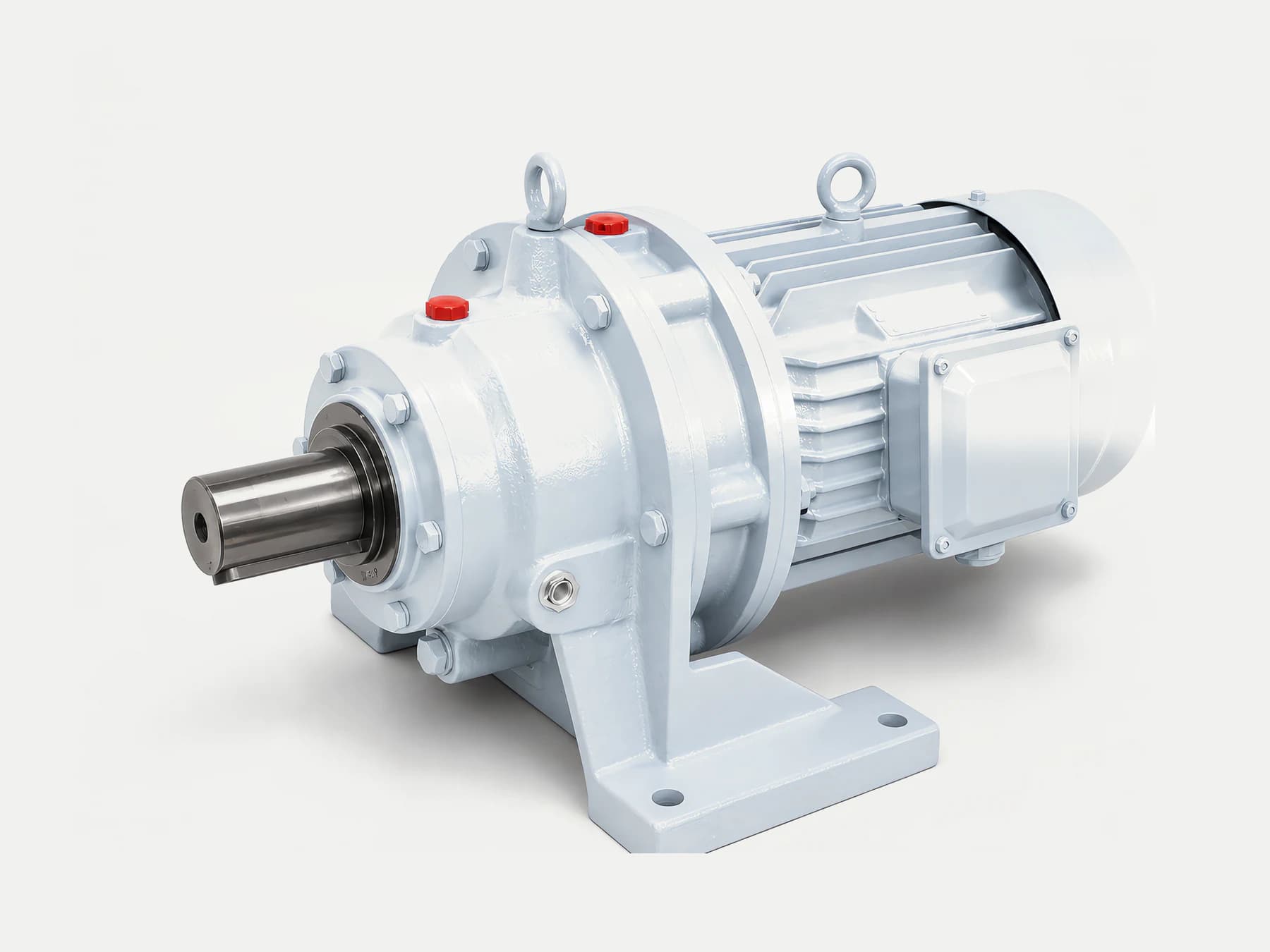
Vibration that appears after a cycloidal reducer has been installed most often comes from the installation side, not from the reducer itself. Three categories are within the installer's control: misalignment, clamping and foundation. The one most often done backwards is clamping — bolts tightened first pull the flange off true. The correct order is: seat the register, snug the bolts lightly, bar the shaft by hand to confirm nothing binds, then tighten in a cross pattern in stages.
That order is the argument of this article. What follows is why it holds, how to measure whether it worked, and how to read the symptom when it did not.
Why a Cycloidal Reducer Is Less Forgiving Than a General-Purpose Gearbox
Two structural facts explain it.
The output is a bolted flange, not a shaft with a coupling. The output flange of a cycloidal reducer bolts directly to the load flange, with no belt or chain sprocket in between. Alignment error therefore enters the reducer without being cushioned. Where a belt or a chain is used, that small amount of give absorbs part of the deviation; a bolted flange leaves no such room.
The cycloidal disc and the ring pins mesh conjugately. The tooth profiles are conjugate, so motion is carried through an exact relative position. Offset the axis and the load goes off-centre — it concentrates on a few ring pins, and wear follows the same pattern.
So installing a cycloidal reducer is not "bolt it up and run it." It is "get the alignment right, and get the clamping even." Those are two separate jobs, and the next sections show that two different parts are responsible for them.
The Three Categories You Can Control
| Category | How it shows up | What controls it |
| Misalignment | Axis offset, flange face tilted | Alignment work and register fit at installation |
| Clamping | Uneven clamp force that pulls the flange out of shape | Tightening sequence and staged tightening |
| Foundation | Base not level, insufficient stiffness | Base levelling and grouting |
What the three share: all of them sit outside the reducer, and none of them can be solved by the reducer itself. The same model, installed well and installed badly, will not feel the same in service.
The Register Locates; the Bolts Only Clamp
A bolted flange joint has two features doing completely different jobs.
| Part | What it does | What happens if it fails |
| Register (pilot boss) — the raised step and its mating recess | Locates — it decides whether the two axes are concentric | Alignment loses its positive location and the bolts have to carry it |
| Bolts | Clamp — they press the two flanges together | The joint face works loose and frets, producing noise |
These two jobs are not interchangeable.
The classic error is to treat the bolts as an alignment tool: tighten them first and expect them to pull the flange into position. A tightened bolt produces clamp force, not locating force. Each bolt pulls as it turns, the flange tilts toward whichever bolt bit first, and the register may not seat fully.
The result is a joint that looks assembled while the register may not be fully seated — the whole joint then stands on bolt friction instead. Unloaded, that can be invisible. Loaded, it vibrates.
The Four-Step Tightening Sequence
- Seat the register first. Push the flange home and confirm the pilot boss is fully into its recess, with the two flange faces in contact by feel.
- Snug the bolts lightly — just enough to carry the flange, with no meaningful clamp force.
- Bar the shaft by hand. Turn it more than one full revolution and confirm there is no binding and no abnormal resistance. This step is the dividing line: if barring binds, alignment is not right — stop tightening and go back to check the register.
- Tighten in a cross pattern, in stages. Work diagonally opposite bolts and bring them up over two or three passes.
Why in stages rather than in one pass? Tighten a joint in a single pass and the clamp force ends up uneven: the bolt tightened first has already pulled the flange down, so the later ones cannot pull it any further; the flange deflects elastically and the deviation is sealed into the assembly. Staging lets the joint seat progressively.
On tightening torque: no values are given here. Torque has to be confirmed per the specific model and the manufacturer's requirements. What this section fixes is the order, not the number.
What to Measure with a Dial Indicator
Whether the alignment is right cannot be settled by feel. Measure it. Three quantities, three expressions.
Total indicator reading (TIR) — one dial indicator, one measuring point, one full revolution; the largest reading minus the smallest:
TIR = max(R) − min(R)R is the indicator reading and TIR is the total indicated runout.
Radial runout converted to eccentricity:
e = TIR / 2e is the eccentricity — the parallel offset. Radial runout is twice the eccentricity, which is why it is halved.
Face runout converted to angular deviation:
Δθ ≈ TIR / DD is the diameter at the measuring point and Δθ is the axis tilt, in radians.
The three do different jobs. `e` describes whether the two axes are offset in parallel; `Δθ` describes whether they sit at an angle to each other. Only the pair together is a complete picture of alignment. Measure one direction and half the problem stays invisible — two axes can read clean at the indicator tip and still be tilted.
What deviation is acceptable? Not given here. It must be confirmed per the specific model and the manufacturer's requirements. This article supplies the method — how to measure and how to calculate — not the pass line.
The First Run
Assembled is not the same as ready for full speed. The sequence is:
| Step | What to do | What to watch |
| 1 | Bar the shaft by hand | Binding, abnormal resistance, unusual noise |
| 2 | Jog | Rotation direction, interference, any noise at the instant of starting |
| 3 | Run at low speed | Whether vibration and temperature rise climb smoothly |
| 4 | Raise speed in steps | Observe at every speed point; do not skip past one |
Why jog? A jog turns the machine for a moment only. If the wiring is reversed or something interferes, the cost is small; a direct start at full speed can cost a machine. Jogging is the cheapest verification available.
Step 4 carries its own point: do not skip past a speed point. Some vibration problems exist only in one speed band — where a component's natural frequency sits close to the running speed, for example. Skip that band and the problem never shows itself.
Four Arrangements, Four Different Installation Concerns
The X series covers horizontal, vertical, direct-motor and double-shaft arrangements, and the installation side is not the same for them:
| Arrangement | What needs extra attention at installation |
| Horizontal | Base level and the oil-level datum |
| Vertical | Verticality, breather position, and sealing where the output faces down |
| Direct-motor | Stricter alignment — no coupling in between to absorb deviation |
| Double-shaft | Both load sides have to be aligned, not just one |
Direct-motor deserves the most attention. With no coupling between the motor shaft and the reducer shaft there is no flexible element to take up error; it lands directly on the two shafts. The same installation accuracy is less forgiving in a direct-motor arrangement. The specific requirement is the one given in the installation manual for that model.
Other derived arrangements beyond these four are covered by the product manual.
Reading the Symptom
| What you see on site | Likely cause | Data to add | Suggested action |
| Vibrates as soon as it is installed, even unloaded | Register not seated, alignment off | Measured face and radial runout | Strip and inspect the register, re-align |
| Smooth unloaded, vibrates under load | Uneven clamp force, foundation not stiff enough | Tightening sequence, foundation condition | Re-check the sequence, inspect the foundation |
| Barring binds | Alignment off, or foreign matter inside | Where in the revolution it binds | Stop tightening, strip and inspect |
| Vibration concentrated at one speed | Close to a component's natural frequency | Vibration record at each speed point | Avoid that band, or change support stiffness |
| Noise on reversal | Joint face loose, fretting | Re-check of the clamped joint | Re-tighten in sequence |
| Vibrates after direct-motor installation | No cushioning, deviation amplified | Measured alignment of both shafts | Re-align to a stricter requirement |
| Oil weeping after vertical installation | Wrong oil-level datum or breather position | Installation orientation, oil level | Re-check level and breather against the orientation |
| One side of a double-shaft unit vibrates | Only one side was aligned | Runout on both sides | Align both sides |
On-Site Checklist
Before installation
- Confirm the model and the arrangement (horizontal / vertical / direct-motor / double-shaft).
- Clean both flange faces; confirm no foreign matter and no burrs.
- Inspect the register for knocks and deformation.
During installation
- Start tightening bolts only after the register is fully seated.
- Snug the bolts only — no meaningful clamp force.
- Bar the shaft more than one revolution and confirm no binding.
- Tighten in a cross pattern in stages; never in a single pass.
After installation, measure
- Measure face runout and calculate
Δθ. - Measure radial runout and calculate
e. - Measure both directions on both shafts, not just one.
First run
- Jog to confirm the rotation direction, then low speed, then step up.
- Record vibration and temperature at each speed point as the baseline for later comparison.
Common Errors and Scope
Common errors
- Using the bolts as an alignment tool. Tighten them first and the register may not seat.
- Tightening without barring the shaft. The binding gets "tightened through" and the deviation stays in the assembly.
- A single tightening pass instead of staged tightening. Uneven clamp force.
- Measuring radial runout only and skipping face runout. The angular deviation is missed.
- Skipping the jog and going straight to full speed. Reversed wiring or interference then costs a machine.
- Skipping a speed point during run-up. Vibration specific to that band is missed.
- Aligning a direct-motor arrangement to the same practice used where a coupling absorbs error. There is no cushioning here, so the demand is stricter.
Scope
- The three categories, the register-and-bolt division of labour, the tightening sequence, the three expressions and the first-run sequence apply to the installation of X/B and WB cycloidal reducers.
- No permissible deviation, alignment deviation or tightening torque values appear in this article. All of them must be confirmed per the specific model and the manufacturer's requirements.
- This article does not quantify how vibration cases divide between the installation side and the reducer; it sets out the factors you control and the checks that find them.
- Installation quality is not a safety function. Good installation reduces vibration and wear, but wherever people, lifting or falling are involved, independent safety devices must still be provided and verified by the machine designer.
- This article does not replace the installation manual for a specific model.
Installation Record
| # | Field | Note |
| 1 | Model and serial number | Include whether X/B or WB series |
| 2 | Arrangement | Horizontal / vertical / direct-motor / double-shaft |
| 3 | Mounting orientation and space | Affects oil level and breather |
| 4 | Load flange data | Register dimensions and fit condition |
| 5 | Joint face condition | Foreign matter, burrs |
| 6 | Measured face runout | Used to calculate Δθ |
| 7 | Measured radial runout | Used to calculate e |
| 8 | Tightening sequence and number of passes | Whether staged, whether cross-pattern |
| 9 | Barring result | Whether it bound, and where |
| 10 | Jog and run-up record | Vibration and temperature at each speed point |
| 11 | Recorded by, and date | Traceability |
Items 6 and 7 are the foundation of the whole method. Without a runout record, "is it aligned" comes down to feel — and feel is not traceable.
About This Article and the Publishing Entity
This article was written by the technical team of Chengfa Reducer (Changzhou) Co., Ltd. (CHINFAR) and published after internal technical review. The X/B and WB series of cycloidal reducers are supplied by Chengfa Reducer (Changzhou) Co., Ltd. CHINFAR products are built and delivered within the joint manufacturing system shared with HUIGUANG.
Related product and background reading:
- Cycloidal reducers
- X series cycloidal reducers
- Industrial gearbox installation, lubrication and first-run checklist
Next Step
Send the eleven items above to sales@chinfar.com. If the unit is already vibrating, the three most valuable items are the arrangement, the measured face and radial runout, and whether barring bound. With those three, the next part to take apart is usually decided in that call.
To be explicit: this article gives no permissible deviation and no tightening torque values — both are confirmed per the specific model and the manufacturer's requirements — and installation quality is not a safety function. Where people or falling loads are involved, independent safety devices are still required.