 ®

Application note
How to Select a Rotary Airlock Drive by Material and Jamming Conditions
Author: CHINFAR Technical Team · Reviewer: Tinyuen (CHINFAR) · Updated: 2026-11-04
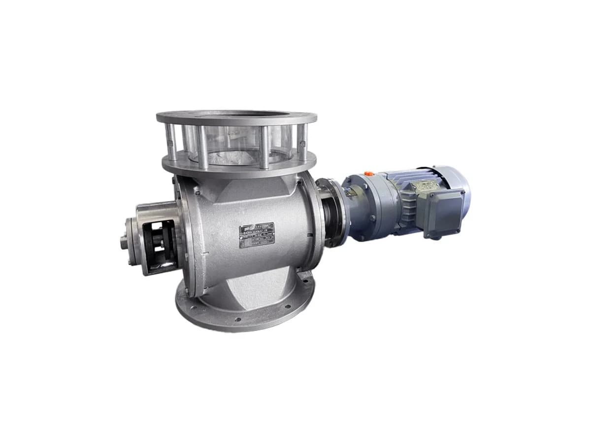
A rotary airlock — a rotary valve or star feeder — meters powder and granular material in pneumatic conveying, in two designs: gravity discharge and pneumatic conveying. Its drive cannot be sized on running torque plus a small margin, for three reasons:
- Jamming is inherent to this equipment. A particle lodged in the rotor-to-housing clearance stalls it; that is not an exception.
- The pockets are full after a shutdown, so start-up must shear the whole pocket.
- Pneumatic conveying adds a differential-pressure load across the rotor.
Check against the jamming torque:
T_jam = T_run · K_jamand size the power from it. A drive sized on running torque will show the problem at the first jam.
1. Three sources of resistance
| Source | When it appears | What it looks like |
| Material shear | Continuously | Tied to the fill factor and to the material properties |
| Start-up on a full pocket | Every start | The pocket is full after shutdown, so the whole pocket must be sheared |
| Differential pressure | Pneumatic conveying designs | The pressure difference across the rotor becomes a resisting torque; close to zero in gravity discharge |
The third row is the one most often left out, because it does not show up in "how heavy the material is" — it shows up in "what system the unit is installed in." The same airlock at a gravity discharge point and on a pneumatic conveying line sees completely different resistance.
2. The four calculations
Discharge rate (mass flow):
Q = n · V_rev · ρ · η_filln is the rotational speed, V_rev the pocket volume per revolution, ρ the bulk density, and η_fill the fill factor.
Jamming torque:
T_jam = T_run · K_jamT_run is the steady running torque, K_jam the jamming factor, and T_jam the torque that may appear when the rotor jams.
Angular velocity:
ω = 2π · n / 60Required power:
P_req = T_jam · ωNote that the last expression uses `T_jam`, not `T_run`. That is the most fundamental difference between this drive and an ordinary conveying drive: a conveyor is sized on running torque with a factor added, an airlock has to be checked directly against the jamming torque.
3. The speed window is set by the material, not by the drive
This point is missed even more often than torque.
Read Q = n · V_rev · ρ · η_fill and it looks as if raising the speed raises the discharge rate. Two opposing limits intervene:
| Speed too high | Speed too low |
The rotor turns faster than the material can fill it, so η_fill drops | The discharge rate falls short of the process requirement |
| Shear action increases and wear accelerates | Material stays in the pocket longer and may arch |
| Service life shortens noticeably with abrasive material | Air leakage behaviour changes in pneumatic conveying |
So a usable window exists, and the material sets it. Free-flowing material with a uniform particle-size distribution gives a wide window; sticky, arch-prone material gives a narrow one.
All the drive can do is deliver enough torque inside that window. It cannot widen the window.
4. Six material properties
This is the part of the sizing input most often reduced to the single question "what material is it". It has to be broken down into seven items:
| Property | What it drives |
| Bulk density | Mass flow at a given volume, and rotational inertia |
| Particle size and shape | Probability of jamming; sets the clearance requirement |
| Moisture content and adhesiveness | Arching, wall build-up, loss of fill factor |
| Temperature | Clearance fits and selection of seal material |
| Abrasiveness | Wear rate of rotor and housing |
| Flowability (arch tendency) | Whether the pockets fill reliably |
| Flammability / combustible dust | Whether the material counts as a combustible dust; where it applies, assess the explosion-protection requirements separately |
Saying "we convey cement" or "we convey fly ash" is not enough — the same material at a different moisture content or a different particle-size distribution jams with a different probability and fills differently.
Where a combustible dust is involved, it has to be assessed against the explosion-protection requirements as well, and that goes beyond the scope of this article.
5. Five protection methods
If jamming cannot be fully avoided, protection has to be fitted. Five common types:
| Method | Advantage | Cost |
| Torque limiter (slip type) | Acts repeatedly, no part replacement | Friction discs need periodic inspection |
| Shear pin | Cheapest, most direct | Every operation means a replacement pin and a stoppage, and the downtime has to be counted |
| VFD current limiting | Adjustable, recordable, and gives a soft start | Needs a variable-frequency drive; higher cost |
| Reverse-jog release | Clears a light jam actively | Needs matching control logic; not for a severe jam |
| Mechanical overrunning clutch | Releases above the set torque and acts repeatedly | Needs setting and reset inspection |
The shear pin row deserves a separate look. It is the cheapest part, but each operation stops the line to change it. Assess it against the jamming frequency on site: at a position that jams often, the repeated shutdowns plus the spare pins can cost more than a repeatable-action device chosen at the start. The cheap item is the part; the expensive item is the downtime.
6. Questions that must be answered before delivery
This section is the most important boundary in the article.
Torque must not be filled in by the supplier.
T_run depends on the material and the structure, K_jam on the material properties, the clearance and the differential pressure, and V_rev and η_fill on the rotor and the material — all of this data lives on the material and equipment side, not on the drive side.
The correct approach is:
T_runfrom material properties and structural data, or measured on comparable equipment;K_jamconfirmed by the process and equipment parties against the material properties, the clearance and the differential pressure;- the drive side then checks the result and specifies the configuration.
Substituting an experience-based torque saves effort now and leaves the risk to the plant.
7. Reading the symptom
| What you see on site | Probable cause | Data still needed | Suggested action |
| Runs normally but jams frequently | Clearance and particle size do not match | Particle-size distribution, clearance dimension | Review the clearance; consider crushing the material or changing the rotor type |
| Every start is laboured | Pockets full after shutdown | Shutdown duration, fill factor | Recalculate torque for the full-pocket start case |
| Stalls outright when it jams | Torque sized on the running value | T_run, K_jam | Check against T_jam instead |
| Shear pin shears repeatedly | Protection setting does not match actual conditions | How often it shears, conditions at the time | Review the setting, or move to a repeatable-action device |
| Discharge rate below requirement | Speed too low, or fill factor too low | Actual η_fill, speed | Check the fill factor first, then consider raising the speed |
| Wear accelerates after raising the speed | Outside the window the material allows | Abrasiveness, rotor material | Return to the window and raise throughput another way |
| Pneumatic conveying position overloads more than the gravity position | Differential pressure adds resistance | Differential pressure | Check the differential-pressure case separately |
| Material arches when it is damp | Moisture content and adhesiveness | Moisture range | Improve the material condition or change the geometry |
8. Site checklist
Material data:
- Confirm the material name and the bulk density.
- Confirm the particle-size distribution and the particle shape.
- Confirm the moisture range and the adhesiveness.
- Confirm the material temperature.
- Confirm the abrasiveness (whether hard particles are present).
- Confirm the flowability or arch tendency.
System data:
- Confirm the design form (gravity discharge or pneumatic conveying).
- If pneumatic conveying, confirm the differential pressure.
- Confirm the target discharge rate.
- Confirm the start-stop method and frequency.
Drive and protection:
- Check the torque against
T_jam, notT_run. - Confirm the protection method (one of the five).
- Confirm that lubrication and heat dissipation are adequate at low speed.
9. Common errors and scope limits
Common errors:
- Sizing on running torque plus a margin. At a jam the jamming torque can approach the stall torque, and the margin is not enough.
- Filling in torque from experience. The effort saved now is the risk left to the plant.
- Describing the material as "what material it is" only. Six items at minimum.
- Ignoring the differential pressure. A pneumatic conveying position does not resist like a gravity discharge position.
- Assuming a higher speed gives a higher discharge rate. The fill factor drops first.
- Ignoring the downtime cost of a shear pin. The cheap item is the part; the expensive item is the stoppage.
- Never mentioning the full-pocket start. The pocket is full after shutdown, so start-up torque is higher than running torque.
Scope limits:
- The three sources of resistance, the four calculations, the seven material properties and the five protection methods here apply to drive-selection preparation for rotary airlocks (rotary valves, star feeders).
- This article gives no numerical torque, jamming factor `K_jam`, speed, material-property or per-revolution pocket volume values; the per-revolution pocket volume range is listed on the rotary valve product page rather than repeated here.
- This article does not fill in torque.
T_runandK_jammust be calculated from material and structural data, or measured. - This article does not rank or count the causes of jams; it supplies material properties and protection inputs only.
- The final selection must be confirmed jointly by the material and process side and the equipment design side; this article does not replace a project-level verification.
10. Sizing input table
| No. | Data item | What it decides |
| 1 | Material name and bulk density | Mass flow and inertia |
| 2 | Particle-size distribution and shape | Probability of jamming and the clearance |
| 3 | Moisture range and adhesiveness | Arching and the fill factor |
| 4 | Material temperature | Fits and sealing |
| 5 | Abrasiveness | Wear rate |
| 6 | Flowability / arch tendency | Whether the pockets fill reliably |
| 7 | Design form | Gravity discharge or pneumatic conveying |
| 8 | Differential pressure | Mandatory for pneumatic conveying |
| 9 | Target discharge rate | Where the speed window sits |
| 10 | Start-stop method and frequency | How much the full-pocket start matters |
| 11 | Protection requirement | Which of the four to fit |
| 12 | Installation space and low-speed lubrication | Configuration choice |
Items 1 to 6 are on the material side; items 7 and 8 are on the system side. If those two groups are incomplete, torque can only be guessed — and a guessed torque is exactly where field overload comes from.
11. About this article and the publisher
This article was prepared by the CHINFAR technical team at Chengfa Reducer (Changzhou) Co., Ltd. and published after technical review by the company. Rotary airlocks are supplied by Chengfa Reducer (Changzhou) Co., Ltd.; CHINFAR products are produced and delivered through the joint manufacturing system shared with HUIGUANG.
Related pages:
- Rotary airlocks (rotary valves)
- Modular geared motors
- Mining and conveying heavy-duty gearboxes
- Contact the CHINFAR technical team
12. Next step
Send the twelve items above to sales@chinfar.com. Items 1 to 6 (material properties) and item 8 (differential pressure) matter most — without those seven, torque can only come from an experience value, and experience values are where overload comes from.
To be clear: this article gives no numerical torque, jamming factor or material-property values; torque must be calculated from material and structural data or measured, and is not filled in here; the final selection must be confirmed jointly by the material and process side and the equipment design side.