 ®
Application note
How to select a gearbox for screw conveyors handling bulk material
Author: HUIGUANG × CHENGFA Transmission Technical Team · Updated: 2026-10-12
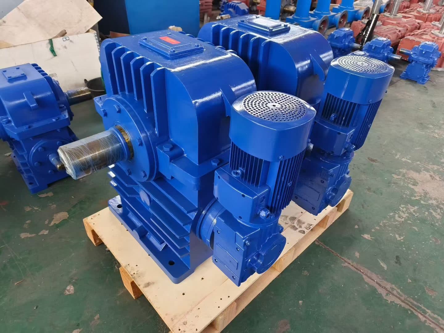
A screw conveyor is one of the few bulk-material machines whose torque demand at the drive shaft is set by the material itself, not by the gearbox. Bulk density, particle size, moisture, abrasiveness and the flight geometry all change the torque that the screw flight asks for every revolution. The reducer has to absorb that variable load, the start-up stall, the inclination effect on a tilted conveyor, and the abrasive or corrosive atmosphere inside the trough.
For OEM equipment manufacturers, system integrators and overseas procurement engineers, the gearbox is selected against a single document: the drive calculation showing screw diameter, flight pitch, filling ratio, required speed, shaft power and the service factor applied to that shaft power. The gearbox selection step is mechanical once that document exists. The most common errors on enquiry are (a) leaving out the service factor entirely, (b) using motor rated power instead of required screw shaft power, and (c) ignoring the start-up condition of inclined or flooded screws.
In this application note we use the motor power band 0.37 to 22 kW, the ratio band 5:1 to 40:1 and the screw diameter band Ø100 to Ø500 mm as the typical envelope for cement, fertilizer, plastic pellet, grain, fly ash, lime and mineral ore screws. Outside this envelope the selection logic is the same, but H / B industrial gearboxes or cycloidal units typically become the right answer; this is summarized in the closing enquiry checklist.
Screw conveyor types and operating conditions
Three screw architectures cover most OEM quotations. The horizontal trough screw, either U-type or tubular enclosed, runs at 15 to 90 rpm and asks for constant torque for a fixed throughput. The inclined screw at 15° to 30° carries the same material but adds a gravity component that raises power draw by 5 to 15% and adds an axial load that the drive bearing must react. The vertical screw lifts material on a screw inside a casing; it acts like a centrifugal pump with a screw and absorbs much more power for a given throughput than the horizontal arrangement.
Flight geometry defines the torque profile. Standard-pitch screws, where flight pitch equals screw diameter, give the baseline. Short-pitch flights at one-half to two-thirds of diameter reduce filling and lower power draw. Variable-pitch flights ease material into the trough and avoid surge at start-up. Ribbon flights are used for sticky material and again reduce the torque the screw asks for. The filling ratio — the cross-section of material in the trough divided by the flight cross-section — is the single most powerful lever the integrator has over load.
As a working rule used by our application engineering team: a filling ratio of 10 to 25% describes a light, well-behaved load on a horizontal screw for grain, plastic pellet or finished cement; 30 to 45% describes a heavy load on inclined, sticky, or abrasive screws that carry ore, fly ash, lime or wet fertilizer. These two bands map directly onto the service factor bands given in the next section, and the OEM should specify which band applies on enquiry.
Drive mounted on trough end vs through-shaft and center-hung
Where the gearbox sits changes the mechanical arrangement and the required gearbox family. A drive mounted on the trough end sits outside the trough, with the screw shaft coupled to the gearbox output by a chain, a coupling, or a flexible spindle. This arrangement is the most common for OEM-supplied trough screws because the gearbox can be moved sideways for service, but it adds a chain or coupling that the integrator must align and guard.
A through-shaft drive puts the gearbox inside the trough, with the screw shaft passing through a hollow-shaft gearbox output and out the other side. Two screw sections share one drive and the trough side becomes available for inspection hatches. This arrangement reduces floor space and alignment work but puts the gearbox inside the abrasive or corrosive atmosphere, so the surface protection rules in Section 8 apply.
A center-hung or shaft-mounted drive hangs the gearbox on the screw shaft itself, supported by a torque arm tied back to the trough frame. This is the cleanest mechanical arrangement for an OEM screw conveyor because there is no chain, no coupling and no alignment to maintain; the gearbox becomes part of the conveyor frame. The selection logic for this arrangement is covered in detail in Section 7, because the hollow-shaft mechanical interface and the torque-arm reaction force drive most of the model choice.
Service factor for screw conveyors
Service factor (SF) is the multiplier applied to the calculated screw shaft power before the gearbox is selected. It absorbs the parts of the load that the screw calculation does not see: start-up inertia, surge loads, abrasive wear that increases friction over time, abnormal operating hours and the small calculation uncertainty in filling ratio. SF is selected from a service-factor table, not guessed from motor size.
For screw conveyors the commonly accepted bands are: SF 1.0 to 1.6 for light duty — horizontal screws carrying grain, plastic pellet, finished cement or sugar, with steady feed, low starting frequency and 8 to 10 hours per day; SF 1.4 to 1.6 sits at the top of this band when the material is mildly abrasive or when starts occur up to several times per hour. SF 1.6 to 2.5 for heavy duty — inclined or vertical screws carrying ore, fly ash, lime, wet fertilizer, clinker dust or sand, with variable feed, sticky surges, high starting frequency and two- or three-shift operation; SF 2.0 is the typical point for inclined abrasive screws; SF 2.5 is reserved for vertical screws or heavily-loaded seasonal applications such as harvest-time grain.
Apply the service factor to the calculated screw shaft power, then check the gearbox catalogue for the rating with the next-higher ratio in the 5:1 to 40:1 range that still meets motor power and the maximum torque of the chosen frame. The full service-factor logic and how it changes the frame size is detailed in "How Service Factor Affects Gearbox Selection"; the unit comparison across R, F, K and S is given in "R, F, K and S Series Geared Motor Differences".
Inline helical (R) and helical-bevel (K) selection
For horizontal and slightly inclined screws in the 0.37 to 22 kW band with ratios in the 5:1 to 40:1 range, the inline helical R-series and the helical-bevel K-series cover the majority of OEM quotes for cement, fertilizer and plastic pellet plants. Both families are mounted by foot or by flange in any of the standard mounting positions M1 to M6 as covered in "Industrial Gearbox Mounting Positions M1 to M6", and both accept standard IEC or NEMA motor inputs.
Use R-series when the screw runs horizontally and the gearbox shaft can sit parallel to the screw shaft. R-series gives the widest ratio spread in a single stage and the highest efficiency of the inline options; it is also the lowest-cost family of the four standard modular lines. For screw conveyors the practical torque range is roughly 100 to 5,000 Nm across the standard R-series frame sizes, which fits every light-duty and most heavy-duty screws in the band.
Use K-series when the screw is inclined and the screw shaft ends at a height different from the motor, or when the trough arrangement requires a right-angle drive. K-series is also preferred when the screw runs at high load and the helical-bevel first stage gives a quieter, more robust gear mesh than a coaxial pair. For inclined abrasive screws in cement plants and fertilizer plants, K-series is the default selection above about 5 kW. The mounting rules and the breather-plug orientation by position are detailed in the mounting-positions article referenced above.
Worm (NMRV / CWU) for inclined and small-output screws
Worm gear units — the NMRV range and the CWU worm-geared-motor combination — fit the lower end of the screw conveyor envelope: small screws at 0.37 to 5.5 kW, ratios from 5:1 up to 40:1 or 60:1, and inclined screws where the right-angle drive and the self-locking characteristic of the worm gear are an advantage. The full mechanical line-up of NMRV and CWU including ratio range, motor flange and output options is given in "Worm Gear Reducer Selection NMRV WP CWU".
The right-angle envelope is the main reason worm units are still selected for screw conveyors, even though helical-bevel K-series can technically deliver the same range. CWU combinations ship as a single worm-geared-motor with a matched IEC input, which shortens the integrator's assembly time and removes the alignment step between the motor and the gearbox. NMRV with a separate motor and coupling is used when the integrator already has a standard motor selected for other parts of the machine.
Two points to watch on screws. First, worm gearboxes do not tolerate abrasive dust on the output oil seal; through-shaft and center-hung worm units must add a felt or lip-seal guard at the trough end. Second, worm efficiency drops at high ratio — confirm that the gearbox-rated power is compared to the SF-applied screw power; if the resulting thermal rating is borderline, step up one frame size rather than one ratio step.
Shaft-mounted hollow-shaft with torque arm
For center-hung or shaft-mounted arrangements, the standard selection is a hollow-shaft gearbox with shrink-disc or keyed bore and a torque arm that reacts the housing torque back into the trough frame. The hollow-shaft mechanical interface is documented in detail in "Solid-Shaft vs Hollow-Shaft Gearbox"; for screw conveyors the hollow-shaft option is almost always chosen, because the screw shaft can be inserted into the gearbox without moving the drive assembly.
Fit the shrink-disc for screws above about 5 kW where shock load or reversing duties are possible; a keyed hollow-shaft with two set screws or a key and a backstop is acceptable on light-duty horizontal screws. Confirm that the trough frame can carry the torque-arm reaction force; for long or inclined screws the reaction force can be several hundred newtons and must be tied back to a stiff part of the frame, not to a sheet-metal guard. The torque arm is part of the OEM scope, not the gearbox scope, and must be shown on the conveyor general assembly drawing.
Shaft-mounted arrangements pair well with helical-bevel K-series for inclined screws, with cycloidal units on heavy inclined or vertical screws above 22 kW, and with worm CWU units on small inclined screws. The cycloidal pin-and-cycloid path gives a slow-output option with very high torque density for vertical screws where the gearbox sits in the same abrasive zone as the screw shaft; this is one of the cases where the ratio range can extend well beyond 40:1 and the heat-rating method replaces the mechanical rating.
Surface protection for cement, fertilizer, abrasive dust
In cement, fertilizer, lime, fly ash, mineral ore and similar plants, the gearbox is exposed to abrasive and corrosive dust that attacks paint, oil seals and breathers. Specify the surface protection against the actual environment, not against a generic outdoor label, because the aggressiveness of cement dust and fertilizer dust is much higher than outdoor humidity alone.
For dry cement, lime or gypsum plants: epoxy-polyurethane topcoat plus a zinc-rich primer, stainless or zinc-plated nameplate, sealed breather plug rather than the standard open breather, and a dust lip-seal on the output shaft. For wet fertilizer, urea-prill or ammonium-sulphate plants: the same coating system plus an additional shaft seal in stainless and a stainless breather, because the medium is both abrasive and mildly corrosive. For outdoor conveyors with weather exposure plus dust, a roof or hood is preferred; if not, the gearbox is supplied in marine-grade coating with stainless hardware on the terminal box.
Oil-seal and breather choices go together with the coating. Lip seals in nitrile or FKM are standard; FKM is required for fertilizer and ore dust above 60 °C gearbox temperature. The breather plug must be on the upper face of the housing in every mounting position, including M1 to M6, and must be remote-mounted or filtered if the gearbox is inside a trough or inside a dust-laden zone.
OEM enclosure and customization notes
Most screw conveyor OEMs take the standard modular gearbox and add three customizations: a specific paint color and label, a customized output bore or shrink-disc for the screw shaft, and a customized mounting position on the gearbox housing. These customizations are routine and lead time is usually unaffected.
Paint: neutral gray or the OEM's corporate color applied over the standard epoxy topcoat, with the OEM part number and the conveyor serial number on the nameplate. Labels: the OEM's brand on the data plate, with the gear ratio, mounting position, oil grade and oil quantity for the actual mounting position shown on the rating plate so that the end user never has to guess at first fill. Output bore: hollow-shaft bored to the integrator's screw-shaft diameter with a keyway and a shrink-disc on the screw side, or with two set screws for light-duty screws.
Export packaging: triple-wall carton with a poly bag and silica-gel desiccant inside, wooden crate or plywood case for ocean freight, and the nameplate sticker repeated on the outside of the crate. For cement and fertilizer plants bound for tropical or humid climates, add a heat-sealed aluminum-foil bag inside the poly bag to keep salt-air moisture out of the breather and seals during the voyage.
Enquiry checklist for screw conveyors
For a clean quotation, send the following items to sales@chinfar.com so that the gearbox selection can be closed in one round:
- Screw diameter (mm), flight pitch (mm), flight type and trough length.
- Material handled, bulk density (kg/m³), particle size, moisture and abrasiveness.
- Required throughput (t/h) and required screw shaft speed (rpm).
- Calculated screw shaft power (kW) and applied service factor (SF 1.0–1.6 light, 1.6–2.5 heavy).
- Motor power, motor speed, motor frame (IEC or NEMA) and supply voltage / frequency.
- Drive arrangement: trough-end, through-shaft or shaft-mounted with torque arm.
- Inclination angle (0°, 15°, 30° or vertical), installation position (M1–M6) and ambient conditions.
- Operating hours per day, starts per hour, two- or three-shift duty and ambient temperature.
- Output-side interface: hollow-shaft bore (mm), keyway, shrink-disc, chain or coupling.
- Surface protection: standard epoxy, cement / fertilizer upgraded coating or marine grade; ambient atmosphere (cement, fertilizer, fly ash, ore, sugar, grain, etc.).
- Mounting position of the breather plug (upper face in M1–M6), oil grade and oil quantity at the actual position.
- For OEM deliveries: required paint color, OEM brand and part number on the nameplate, label layout, packaging and destination port.
Send drawings or photographs of the trough layout when available; one sketch with motor center height, trough-end position and torque-arm reaction point saves at least one round of gearbox selection.
Gear reducer selection for screw conveyors is a routine OEM exercise once the screw calculation, the service-factor band and the mechanical arrangement are all clear. The HUIGUANG × CHENGFA joint-manufactured R-series inline helical, K-series helical-bevel and NMRV / CWU worm units, backed by shaft-mounted and cycloidal options for heavier duties, cover the full 0.37 to 22 kW cement and fertilizer envelope in the 5:1 to 40:1 ratio range with screws from Ø100 to Ø500 mm. The HUIGUANG × CHENGFA Transmission joint brand supports OEM equipment makers, system integrators and overseas procurement engineers on screw conveyor drives for bulk-material handling worldwide, with engineering documentation, OEM labeling and export packaging arranged as part of the standard enquiry process.