 ®
Application note
How to select a gearbox for vibratory and apron feeders in mineral processing
Author: HUIGUANG × CHENGFA Transmission Technical Team · Updated: 2026-10-13
Feeder load profile and eccentric-weight induced torque
Vibratory feeders and apron feeders are not constant-torque loads. Their drive power is set by the dynamic reaction of eccentric weights, the moving mass of the trough or pan, and the bulk material being metered onto the conveyor or crusher downstream. For volumetric feeders handling 50–2000 tph of crushed stone, ore, sinter, coal, or fertilizer, the gearbox must absorb a sinusoidal torque ripple every cycle, a step change in load when the feeder starts under a full trough, and the shock of tramp metal or bridging ore. Eccentric weights between 10–50 kg per shaft running at 700–960 rpm create peak torques that can reach two to three times the running mean. A motor running at constant speed cannot simply be coupled to this load; the gearbox is the mechanical filter that converts motor torque into controlled feeder motion. For OEM equipment manufacturers building screens, crushers, conveyor skids, and complete mineral processing or bulk-material-handling plants, selecting the right industrial gearbox is therefore a packaging decision as much as a sizing decision. It determines start-up behavior, VFD compatibility, mounting footprint, and the spare-parts philosophy that the end user will live with for the next ten years.
Feeder types and operating conditions
Three feeder architectures dominate the OEM enquiry desk. The first is the single-shaft eccentric vibratory feeder used for light to medium duty at 50–500 tph, typically driven by one 1.5–11 kW motor through a single reduction unit and a single pair of eccentric weights. The second is the dual-shaft linear or counter-flow vibratory feeder used at 200–2000 tph for crushers, screens, and bin discharge, normally driven by two motors of 7.5–75 kW that must be phase-locked so the eccentric weights add or oppose as the design requires. The third is the apron feeder, a heavy-duty chain-and-pan conveyor that meters coarse ore from a primary crusher stockpile, with drive power from 11–75 kW and chain-pan masses of several tonnes that must be accelerated every start. Each architecture imposes a different duty on the gearbox. The single-shaft feeder accepts a moderate start-up shock, the dual-shaft feeder requires synchronized motors and matched gearboxes with low backlash so the eccentric forces stay in phase, and the apron feeder demands high breakaway torque and often a fluid coupling or soft-starter to cushion the chain. Across all three, the operating environment is harsh: dust from limestone, sinter, or coal dust; water spray from washdowns or rain; and ambient temperatures from −20 °C in northern winter sites to +50 °C in steel-mill or foundry service. Cross-reference the practical limits in our application note "How Service Factor Affects Gearbox Selection" when rating any of these drives.
Variable-frequency drive and start-up duty
Most OEM feeder packages now ship with a variable-frequency drive (VFD) as standard. The VFD lets the operator trim the feed rate to match downstream crusher power draw or screen efficiency, run a slow ramp-up to seat the eccentric weights, and synchronize two motors on a dual-shaft feeder without mechanical phase gearing. A VFD-driven motor also reduces the locked-rotor current, which on a 75 kW feeder would otherwise produce a voltage dip large enough to disturb the rest of the plant. The penalty is thermal: an inverter-duty motor fed by a modern VFD with a switching frequency above 4 kHz sees additional winding stress and must be specified to thermal class F (155 °C) with a class B (130 °C) rise, or fitted with an insulated bearing and a shaft grounding ring to protect the gearbox bearings from fluting damage caused by VFD-induced shaft currents. When the enquiry specifies a VFD, the gearbox rating must be confirmed against the motor's full speed range, not just 50 or 60 Hz. Below 20 Hz, motor cooling fans lose effectiveness and the motor may need a separately driven fan; the gearbox selection should be flagged so that the chosen K-series helical-bevel, HB industrial gearbox, or modular geared motor is not de-rated by an under-cooled motor on the same skid. For apron feeders with very high start-up inertia, a fluid coupling between the motor and the gearbox can replace or supplement the VFD ramp; the OEM enquiry should make clear whether the soft-start is electronic or hydrodynamic, because that choice changes both the gearbox service factor and the coupling selection.
Service factor for feeder duty
Feeder duty rarely falls into a clean catalog category, so the service factor (SF) is where most of the engineering judgment lives. As a working rule for OEM selection on eccentric-weight vibratory feeders and apron feeders: specify a minimum service factor of 2.0 for light-duty volumetric feeders handling fines and uniform material; 2.0–2.5 for standard dual-shaft feeders and apron feeders feeding jaw or cone crushers; and 2.5 or higher for heavy-duty apron feeders in primary crushing with surge loads and tramp metal. Use 2.5 as the default for any 24-hour mineral processing application unless the OEM can document otherwise. SF must be applied to the gearbox's mechanical rating, not to motor nameplate, and must be checked against both thermal capacity and peak torque. The thermal check matters most for continuous feeders at 100 % stroke; the peak torque check matters most at start-up and during material bridging. Reserve at least 20 % output torque above the calculated peak for eccentric-weight feeders, and at least 30 % for apron feeders, because both routinely deliver shock loads that catalog curves do not show. Catalog ratings from K, S, F, and HB series assume uniform loading; feeder duty is never uniform. Match the gearbox size to the calculated SF, then re-check it against the related selection guide "Industrial Gearbox Selection Inputs" before issuing a quotation.
Drive arrangement (single, dual, counter-flow)
The drive arrangement is fixed by the feeder maker and is rarely negotiable, but it does drive the gearbox selection. A single-shaft eccentric feeder can use a single foot-mounted or flange-mounted helical or helical-bevel gearbox with a standard motor. A dual-shaft feeder where the eccentric weights must add forces along the line of the trough (linear vibration) or oppose them (counter-flow) needs two gearboxes whose ratios match within 1 % so the eccentric shafts stay synchronized; backlash on the gearbox, slop in the motor mounting, and stretch in the V-belts (if used) all push the shafts out of phase. For tight synchronization, prefer a parallel-shaft or helical-bevel unit with low backlash gearing, fixed center mounting, and direct coupling to the eccentric shaft rather than belt drive. A dual-motor counter-flow feeder where the two eccentric shafts rotate in opposite directions to create a conveying or screening motion needs gearboxes mounted on opposite sides of the trough; the standard M1–M6 mounting positions covered in "Industrial Gearbox Mounting Positions M1 to M6" all remain available, but the breather, oil-level plugs, and oil-drain positions must be mirrored so both units share the same maintenance procedure. For large dual-motor feeders at 30–75 kW per side, an HB industrial gearbox with parallel-shaft or helical-bevel gearing and a hollow output shaft is the primary recommendation; a K-series helical-bevel unit is the compact backup where the feeder skid is space-limited.
Mounting position and backstop
Feeder applications rarely need a backstop, but apron feeders do. A stopped apron feeder under a loaded pan will roll backward if the drive motor coasts down and the chain is held by material above; a backstop integrated in the gearbox prevents the reverse rotation that would otherwise require an external brake or ratchet. When specifying a backstop, choose a non-contact sprag or roller-type unit rated for the full output torque with the same service factor as the gearbox, and confirm that the backstop allows the gearbox to be back-driven by an inching motor for maintenance without damage. Mounting position is the second silent selection point. Most feeder OEMs specify M3 (foot-mounted, shaft horizontal) or M4 (flange-mounted, shaft vertical down) for compact skid packaging, but on apron feeders the M5 or M6 positions often give a cleaner chain-shaft alignment. Whichever position is chosen, the breather plug must be at the highest oil point and the drain at the lowest; the oil-level plug must remain accessible without removing guards; and the output-shaft oil seal must be the double-lip or taconite type for dust service. For high-inertia start applications, the mounting hardware should include a torque arm or dowel pin to absorb the reaction torque of the VFD ramp.
Corrosive / wet / dusty environments
Vibratory and apron feeders in mineral processing plants, port terminals, fertilizer plants, and cement works live in environments that destroy ordinary gearboxes. Dust ingress through the input and output seals is the leading cause of premature failure on eccentric-weight feeders, where the trough vibration continuously agitates airborne fines. Specify dust seals on both ends of the output shaft, a sealed motor adapter or input cover where the motor mounts, and a magnetic drain plug to capture wear particles. In washdown or outdoor service, specify a synthetic oil with good water-demulsibility, an extension breather that can be piped up and away from the dust zone, and an epoxy or polyurethane internal coating on the housing. For coastal, fertilizer, or chemical service, the gearbox housing should ship with a two-part epoxy primer plus a polyurethane top coat rated for the chemical exposure, with stainless or zinc-plated fasteners and an aluminum or stainless nameplate. Where the feeder is exposed to salt spray or acidic dust, a stainless-steel shrink-disc option on the hollow output shaft is preferred over a plain keyed connection, because it removes the keyway as a corrosion site and makes field removal possible without a puller.
OEM enclosure and customization notes
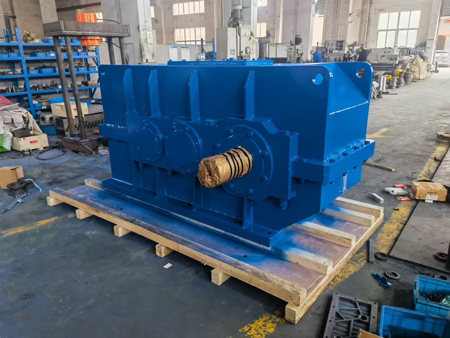
For OEM equipment manufacturers selling feeder packages globally, the gearbox envelope is often as important as its rating. A modular geared motor with integrated motor and inverter-duty specification, factory-filled oil, and pre-drilled mounting feet lets the OEM assemble the feeder on a single skid with a minimum of alignment work. For higher-power dual-motor feeders, an HB industrial gearbox with hollow output shaft and shrink-disc option gives the cleanest mechanical package and the shortest overall length; the K-series helical-bevel unit is the alternate choice when a right-angle layout saves skid space. Customization the OEM should consider requesting at the enquiry stage: thermal class F motor with class B rise and insulated bearings, VFD-rated winding and shaft grounding ring, double-lip output seals, taconite seals where dust is severe, synthetic oil filled at the factory, breather extension piped to the outside of any enclosure, epoxy or polyurethane exterior coating in the customer-specified color, OEM labels and serial-number plates in the customer's language and format, and export packaging suitable for container or flat-rack shipment with desiccant and vapor corrosion inhibitor (VCI) bags. For service in cold climates, request low-temperature seals and synthetic oil rated to −30 °C; for foundry or steel-mill service, request high-temperature seals, mineral oil rated to +90 °C, and a paint system rated to +200 °C surface temperature. The differences between R, F, K, and S series geared motors are summarized in the related note "R, F, K and S Series Geared Motor Differences"; for feeder duty the rule of thumb is K-series helical-bevel as the compact choice, HB industrial gearbox as the heavy-duty choice, and S-series or helical worm as a small-footprint option only on volumetric feeders below 5 kW.
Enquiry checklist for feeders
Before sending an enquiry to HUIGUANG × CHENGFA, gather the following items so the gearbox can be selected against the real feeder duty rather than against a catalog curve. (1) Feeder type — single-shaft eccentric, dual-shaft linear, dual-shaft counter-flow, or apron. (2) Trough or pan dimensions, moving mass, and full-load mass. (3) Eccentric weight per shaft, total weight, and shaft speed. (4) Required capacity in tph and bulk density of the material. (5) Motor power, voltage, frequency, and VFD specification including switching frequency and ramp profile. (6) Service factor required by the OEM, or confirmation that the standard 2.0–2.5 feeder range is acceptable. (7) Mounting position (M1–M6), shaft orientation, and whether a backstop or brake is required. (8) Output connection — keyed solid shaft, hollow shaft with shrink disc, or flange. (9) Environment — ambient temperature, dust, water, chemicals, altitude, and any washdown or outdoor exposure. (10) Certification, labeling, surface coating, and packaging requirements for the destination country. (11) Spare-parts and service philosophy the OEM wants to support over the feeder life. With this information the selection moves from a generic catalog number to a defined, traceable feeder drive.
Selecting a gear reducer for a vibratory feeder or apron feeder is a packaging decision as much as a sizing decision. The right combination — an HB industrial gearbox or K-series helical-bevel unit driven by an inverter-duty motor through a VFD, with the correct service factor, mounting position, backstop, sealing package, and surface coating — is what lets the OEM ship a feeder that starts cleanly, runs in phase, survives the dust, and earns its keep for the next decade. As the joint manufacturing brand of HUIGUANG and CHENGFA Transmission, HUIGUANG × CHENGFA supplies this integrated feeder drive package to OEMs, system integrators, and overseas procurement engineers building mineral processing plants, port bulk-handling terminals, cement and aggregate plants, and fertilizer and sinter lines. Our role is to translate the feeder duty on your drawing into a gearbox rating, a mounting arrangement, and a customization plan that fits your skid, your VFD, and your destination market, with the documentation and spare-parts support that global OEM programs require.