 ®
Application note
How to select a gearbox for belt conveyor systems in mining
Author: HUIGUANG × CHENGFA Transmission Technical Team · Updated: 2026-10-09
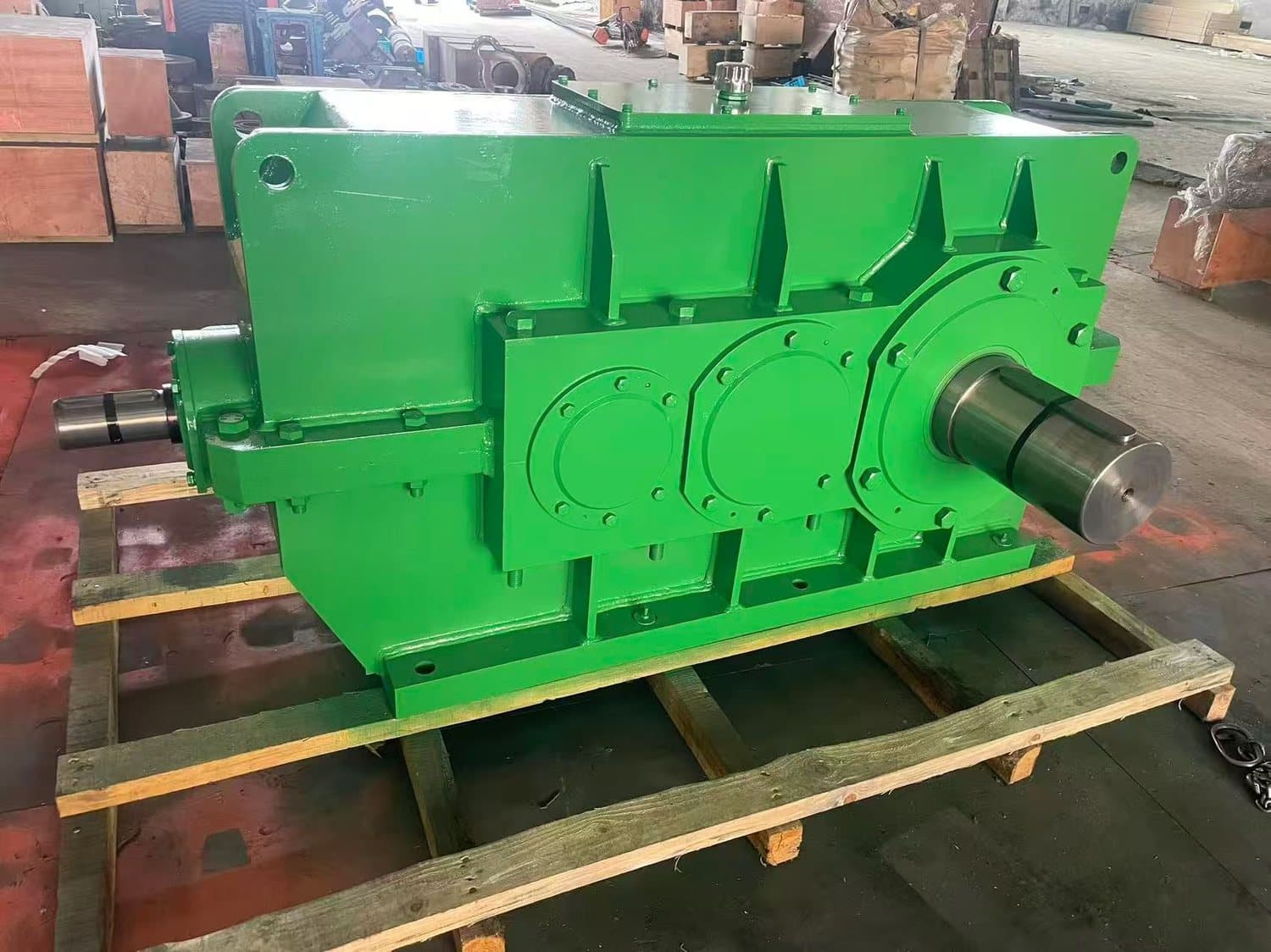
Belt conveyors carry bulk material on a continuous belt supported by idlers, and they are the most common machine in any mining, mineral processing, or bulk-material-handling plant. Selecting the drive gearbox is straightforward once the conveyor geometry is fixed — but at the OEM quotation stage the geometry is usually fixed and the gearbox is the packaging decision that ties motor, soft-start, brake, backstop, layout, and spare-parts philosophy together. For OEM equipment builders, system integrators, and overseas procurement engineers, this application note covers the practical envelope of belt-conveyor drives, the gearbox families that fit, and the engineering decisions that show up on the enquiry sheet.
Motor power alone is not the deciding number. For a belt conveyor the gearbox specifier needs belt width, belt speed, conveyor length and lift, material bulk density, trough angle, idler spacing, ambient operating temperature, ambient dust load, duty cycle in hours per day, starts per hour, the proposed drive arrangement (single, dual, or tripper), and the layout of the drive station relative to the head pulley. Service factor is then applied to the calculated conveyor drive power to absorb the parts the belt calculation does not see: starting friction of cold belts, alignment error, varying load, and abnormal operating hours. The gearbox is selected mechanically once that envelope is closed.
This note uses the envelope 4 to 315 kW motor power, 6 to 30 m/s belt speed, conveyor length 30 m to 5 km, and lift up to 60 m as the typical OEM band for coal, iron ore, bauxite, clinker, limestone, copper concentrate, aggregate, fertilizer, and grain. Outside this envelope the same logic applies but with H/B industrial gearboxes, planetary units, or shaft-mounted units becoming the right answer instead of the modular geared-motor range, as covered in the closing enquiry checklist.
Belt conveyor types and operating conditions
Five belt-conveyor architectures cover most OEM enquiries. The troughed belt conveyor, the most common, carries dry bulk on a belt idlered in a 20° to 45° trough, with motor power typically 4 to 250 kW and belt speed 1 to 6 m/s for mining duty. The pipe belt conveyor forms the belt into a pipe using special idlers for sealed transport of fine or dusty material at 200 to 2000 tph, normally 22 to 250 kW and 1 to 5 m/s. The shiftable or mobile conveyor, common in stockyards and ports, is a wheel-mounted or crawler-mounted conveyor that can be repositioned along a stockpile, with 7.5 to 132 kW drives and belt lengths from 30 to 80 m. The cable belt conveyor uses cables as the tension element and rubber or PVC as the load-carrying surface, with one or two drives at 75 to 600 kW each, used for very long overland or cross-country runs. The tripper conveyor is a short cross-belt with a tripper car that discharges at multiple points along a main conveyor, typically 11 to 90 kW with frequent start-stops.
Operating conditions vary with material. Coal, limestone, aggregate and clinker are abrasive and dusty at transfer points. Iron ore is heavy (bulk density 1.6 to 2.4 t/m³) and produces high belt pull. Copper concentrate is fine and corrosive if it carries moisture. Fertilizer and urea-prill can degrade with humidity. Across the board, ambient temperature covers −30 °C in northern winter to +50 °C in tropical or foundry service, and most mining installations are outdoors in dust, rain, or marine air. The gearbox specification must be set against the actual environment, not against a generic outdoor label.
Duty cycle separates the equipment classes. Class I covers light-duty bulk handling under 8 hours per day with fewer than 5 starts per hour; service factor 1.0 to 1.25 is normal. Class II covers two-shift aggregate and cement plants with up to 10 starts per hour; service factor 1.25 to 1.5. Class III covers mining operations at 16 or more hours per day with moderate surge loads; service factor 1.5 to 1.75. Class IV covers heavy-duty mining duty with regular start-stops, tripper operation, or inclined conveyors above 15°; service factor 1.75 to 2.0. Class V covers continuous 24-hour mineral-processing service with peak loads up to twice nameplate; service factor 2.0 to 2.5.
Drive arrangement and mounting layout
Drive arrangement is fixed by the conveyor layout. A single-drive conveyor uses one motor-gearbox set mounted at the head pulley, with the gearbox either shaft-mounted on the pulley shaft via a hollow-shaft and shrink-disc, foot-mounted on a baseplate beside the pulley, or flange-mounted to a fabricated pedestal below the pulley. Single-drive covers most conveyors up to about 250 kW and most belt widths up to 1400 mm; above this, single-motor drives become oversized and the rest of the system stops being the bottleneck. A dual-drive conveyor uses two motor-gearbox sets in tandem at the head pulley, sized so each drive can carry the full conveyor load alone; the second drive is for redundancy and overload. Each gearbox must be rated for the full rated power plus the calculated service factor, and the two gearboxes must be selected so their ratios match within 0.5 percent to avoid belt-skew and uneven load share. Dual-drive covers conveyors above 250 kW and is the standard layout for 1800 mm and wider belts. A tripper-conveyor drive uses a single drive with frequent starts per hour and a brake that stops the belt precisely under load; the gearbox absorbs the energy of each start and stop.
Mounting layout drives the gearbox family and the output interface. A hollow-shaft output on the gearbox slides directly over the pulley shaft and locks with a shrink-disc or torque-arm, removing the alignment and coupling work. A solid-shaft output drives through a gear coupling or chain coupling into the pulley-shaft input, and is preferred on very heavy drives where the coupling absorbs any shock between motor and pulley shaft. Through-shaft drives, where the motor-to-pulley shaft passes straight through the gearbox, are occasionally used on tripper cars where the layout is constrained. Whichever layout is chosen, mounting positions M1 to M6 per industry convention determine the breather-plug, oil-level, and drain-plug orientation; the related guide Industrial Gearbox Mounting Positions M1 to M6 documents the breather-plug location by position.
Service factor for conveyor duty
Service factor (SF) for belt conveyors is selected against the operating class above, then refined against the actual duty profile. The conveyor calculation gives a base drive power from belt width, belt speed, conveyor length, lift, and material density; SF is the multiplier that turns the base power into the gearbox rating. As a working rule for OEM selection on troughed, pipe, shiftable, and cable-belt conveyors: SF 1.25 for light-duty aggregate and bagged-cement conveyors; SF 1.5 for steady coal, iron ore, and limestone conveyors; SF 1.75 for heavy ore and overland conveyors with trips and starts; SF 2.0 to 2.5 for inclined conveyors above 15°, mobile conveyors with frequent relocations, and tripper conveyors with frequent start-stops. The full background and the thermal-versus-mechanical rating logic is covered in the related note How Service Factor Affects Gearbox Selection.
SF must be applied to the gearbox mechanical rating, not to motor nameplate, and must be checked against both thermal capacity and peak torque. For belt conveyors the thermal check usually passes once the SF band is set correctly; the peak-torque check is what catches the dual-drive or tripper conveyor where starting friction can momentarily push the gearbox past its rated torque. The OEM enquiry should give the calculated drive power, the applied SF, the calculated peak torque during start-up, and the duty cycle including hours per day and starts per hour. Match the gearbox size to the calculated SF, then re-check it against the related selection guide Industrial Gearbox Selection Inputs before issuing the quotation.
Gearbox selection for troughed belt conveyors
For troughed belt conveyors in the 4 to 250 kW range and belt widths up to 1400 mm, the modular geared-motor range (R, F, K, S series) covers most OEM enquiries from cement, aggregate, fertilizer, and grain plants. R-series inline helical gives a coaxial layout that suits shaft-mounted drive stations; F-series parallel-shaft gives an offset layout that suits baseplate drives beside the head pulley; K-series helical-bevel gives a right-angle layout that fits pedestal drives below the pulley; S-series helical-worm is reserved for low-power fertilizer and grain conveyors below about 11 kW. The selection logic by duty and layout is summarised in the related note R, F, K and S Series Geared Motor Differences.
Above 250 kW the modular range is supplemented or replaced by H/B industrial inline gearboxes with ratios from 8:1 to 100:1 across two stages, supporting motor powers up to 630 kW per unit. Dual-drive at the head pulley using two H/B units is the standard layout for long and wide conveyors. Cable belt conveyors with single drives above 500 kW typically move to P-series planetary units with hollow-shaft output, providing very high torque density in a compact package, with ratios from 30:1 to 250:1. Underground conveyors in coal mines add an explosion-proof (ATEX / IECEx) requirement on the motor and an extended temperature envelope; H/B and P-series both ship in ATEX-rated versions. The H/B industrial line and the P-series planetary line are documented in the related guides Industrial Gearbox Selection Product Guide and P-Series Planetary Gearbox Overview.
For the OEM, the practical selection rule at the enquiry stage is: modular R/F/K/S series for 4 to 250 kW single-drive conveyors up to 1400 mm width; H/B industrial for 250 to 630 kW single-drive and 400 to 800 kW dual-drive conveyors; P-series planetary for very long overland and cable-belt conveyors above 500 kW where torque density matters. Concrete conveyor projects above 5 km length or above 60 m lift add a secondary gearbox on the tail pulley for cable tension; the layout is then a dual-drive head plus a tail assist, with each drive sized independently against its own motor and SF.
Gearbox selection for pipe conveyors and shiftable conveyors
Pipe conveyors wrap the belt into a pipe using six or eight special idlers and run at reduced belt speed because of the higher rolling resistance. They handle fine, dusty, or environmentally sensitive material (cement raw meal, fly ash, copper concentrate, urea, fly-ash, food-grade powders) at 200 to 2000 tph. The drive power is typically 1.5 to 2.2 times that of an equivalent troughed belt, with single or dual drive at 22 to 250 kW per motor. The gearbox selection logic is the same as troughed belt but with the SF band moved up by one notch because of higher peak loads at start-up and during pipe deformation. Modular K-series is the standard for 22 to 110 kW pipe conveyors; H/B industrial supplements at 132 to 250 kW per drive. The OE enquiry should flag the pipe-conveyor layout because the drive station layout is constrained by the pipe-forming and pipe-opening idler sets.
Shiftable or mobile conveyors in stockyards and ports are wheel- or crawler-mounted units that can be repositioned along a stockpile or a barge line. Belt widths are 800 to 1400 mm, lengths 30 to 80 m, drive power 7.5 to 132 kW. The gearbox sees the full conveyor operating envelope plus mobile-plant duty: frequent repositioning, outdoor exposure, and elevated ambient dust. The standard selection is modular R-series or K-series with foot-mounted arrangement and a hollow-shaft output. The gearbox must be IP55 minimum, with sealed breathers, dust lip-seals, and a marine-grade coating because the mobile plant sits outdoors in stockyard or port service. SF is set to 1.5 to 1.75 because the conveyor is repositioned daily.
Motor matching, soft-start, and electrical considerations
On a belt conveyor the motor and gearbox are tuned together. A standard three-phase induction motor at 4 to 6 poles runs the conveyor at nominal speed; a two-pole motor at 50/60 Hz gives the higher belt speeds seen on overland conveyors. A VFD-driven motor adjusts belt speed to match feed conditions and reduces starting current, but the gearbox rating must be confirmed against the motor's full speed range, not just 50 or 60 Hz. Below 20 Hz motor cooling fans lose effectiveness and an inverter-duty motor with a separately driven fan is needed; the gearbox is not de-rated but the motor thermal class must be confirmed. Where the enquiry specifies a VFD, the gearbox is generally rated for the full rated torque across the speed range, with the VFD ramp profile and switching frequency declared in the OE order.
Soft-start is a separate decision from motor selection. Fluid couplings slip during start-up and reduce the gearbox start-up torque to a controlled fraction of motor torque; the gearbox can be sized for the running torque instead of the start-up peak, but the coupling itself becomes a spare-part item and must be rated for the energy dissipated during each start. Electronic soft-starters with thyristor or IGBT ramps are a common alternative; they reduce motor starting current without slipping a fluid coupling, but they pass the full start-up torque to the gearbox, so the SF must still cover the start-up peak. Wound-rotor slip-ring motors are an older alternative still in service on heavy conveyors; they reduce the gearbox start-up shock by reducing motor torque at low slip. The choice between fluid coupling and electronic soft-start changes the gearbox SF band; the OE enquiry should make this explicit so the SF can be set correctly.
Brake and backstop are belt-conveyor-specific. A held conveyor will roll backward under load if the motor is de-energised, especially on inclined conveyors; a non-contact sprag or roller-type backstop in the gearbox prevents reverse rotation and acts as a redundant safety device. A disc brake on the gearbox motor-side provides controlled stop and holds the belt during stop. For conveyors up to 45° lift the backstop alone is usually sufficient. For steeper conveyors or safety-critical applications, the backstop is combined with a hydraulic fail-safe brake on a motor-side or intermediate-shaft brake flange. The related guide Industrial Gearbox Mounting Positions M1 to M6 documents the backstop and brake interface options.
Backstops, fluid couplings, and shaft-mounted options
The backstop is the unsung component of belt conveyor drives. On a horizontal conveyor the backstop is not strictly needed, but on a 5° to 45° inclined conveyor it is essential — a loaded belt rolling backward can destroy the drive in seconds. The preferred arrangement is a sprag-type backstop integrated into the gearbox, selected for the full output torque with the same SF as the gearbox and confirmed to allow back-driving by an inching motor for maintenance without damage. Ratchet backstops are reserved for low-power conveyors only.
Fluid couplings sit between the motor and gearbox and serve three purposes: they reduce the gearbox start-up torque to about 1.5 to 2.0 times the running torque (compared with three to four times for a direct-on-line start), they act as a mechanical fuse if the belt stalls (the coupling slips at a calibrated torque and the motor continues to run, protected), and they provide a soft start-up that is independent of the motor electrical ramp. The penalty is a 5 to 15 percent slip loss at running speed, which increases motor power draw at the chosen belt speed and adds a steady-state heat dissipation requirement on the coupling. The OE enquiry should declare whether the fluid coupling is in scope; the gearbox SF then reflects the actual start-up torque after the coupling.
Shaft-mounted hollow-shaft arrangements are the cleanest mechanical package for belt conveyors because the gearbox slides onto the pulley shaft and locks with a shrink-disc, removing the alignment and coupling step. They are especially suited to foot-mounted K-series or H/B industrial units on troughed belt conveyors above about 75 kW. The shrink-disc must be selected against the pulley-shaft diameter and material; a keyed shaft-mounted arrangement is acceptable for light-duty conveyors below 30 kW but should be avoided on heavy drives where the key and keyway become a fatigue location. Hollow-shaft-with-shrink-disc and the alternative solid-shaft with coupling are covered in detail in the related guide Solid-Shaft vs Hollow-Shaft Gearbox.
OEM enclosure and customization notes
OEM customers building belt conveyors usually need more than a catalogue gearbox. Typical customisations are: a non-standard input flange to match a particular IEC or NEMA motor frame; a non-standard output shaft bore or shrink-disc fit for a specific pulley shaft; an integrated sprag or roller-type backstop; an integrated hydraulic disc brake or a brake-mounting flange for an external brake; a special mounting position outside the standard M1 to M6 set; a non-standard low-speed or high-speed ratio; an OEM-specific paint colour, label, and serial-number plate; and a documentation package including the test certificate, installation drawing, lubrication schedule, and spare-parts list. OEM label, packaging, and documentation are part of the standard scope; lead-time impact for the most common customisations is short and does not affect serial production.
Surface protection for mining conveyors is a standard part of the quotation. The surface coating system starts with a zinc-rich primer at 60 to 80 µm, an epoxy intermediate coat at 100 to 150 µm, and a polyurethane top coat at 40 to 60 µm; total dry-film thickness of 200 to 280 µm. For tropical or marine service the polyurethane top coat is replaced by a polysiloxane or a fluoropolymer top coat at 40 to 60 µm and the standard colour is light grey or white to reduce solar heat gain. The coating system is specified per ISO 12944 corrosivity category C4 for coastal industrial and C5-M for offshore marine. The breather plug is upgraded to a desiccant type for outdoor service, the oil-level and drain plugs are upgraded to magnetic type with sealed washers, and the inspection cover is sealed with a continuous gasket. Export packaging is a fumigated wooden crate with VCI film and desiccant bags for ocean freight.
Export documentation for OEM customers typically includes CE / ISO 9001 / EAC declarations depending on the destination, test certificates (no-load run, noise, vibration, oil-tightness, paint thickness), material certificates for gears and shafts, dimensional inspection reports, installation drawings, lubrication schedules, and spare-parts lists. For ATEX-classified conveyors in coal-preparation plants or underground service, the gearbox and motor are supplied against a documented conformity dossier including the nameplate marking, the operating-temperature range, and the dust or gas group. The OE enquiry should specify the destination country so the supplier can match the documentation and certification.
Enquiry checklist for belt conveyors
For a clean quotation, send the following items to sales@chinfar.com so that the gearbox selection can be closed in one round. (1) Conveyor type — troughed, pipe, shiftable, mobile, cable belt, or tripper. (2) Belt width, belt speed, conveyor length and lift. (3) Material handled and bulk density in t/m³. (4) Calculated drive power in kW and applied service factor. (5) Motor power, motor speed, motor frame (IEC or NEMA) and supply voltage / frequency. (6) Drive arrangement — single, dual, or tripper; tail assist if applicable. (7) Inclination angle, trough angle, idler spacing, transfer-point configuration. (8) Operating hours per day, starts per hour, ambient temperature, ambient dust level. (9) Output-side interface — hollow-shaft with shrink disc, keyed hollow-shaft, solid-shaft with coupling. (10) Soft-start type — direct-on-line, fluid coupling, electronic soft-starter, VFD, or wound-rotor slip-ring. (11) Brake and backstop requirements — none, integrated sprag, hydraulic disc brake, or combined. (12) Surface protection, OEM colour and label, ATEX / IECEx zone if applicable, destination country for certification.
Send layout drawings of the drive station and head pulley when available; one sketch with motor centre height, gearbox mounting position, output shaft arrangement, and brake / backstop interface saves at least one round of gearbox selection. For replacement projects, provide the original drawing or mounting dimensions, the existing motor and coupling arrangement, and the actual operating conditions.
Belt-conveyor drive selection is a routine OEM exercise once the conveyor geometry, the service-factor band, and the drive arrangement are all clear. The HUIGUANG × CHENGFA joint-manufactured modular R/F/K/S geared-motor range covers the 4 to 250 kW troughed belt and pipe belt envelope; the H/B industrial line extends the selection to 630 kW single-drive and 800 kW dual-drive conveyors; the P-series planetary line supports cable belt and very long overland conveyors above 500 kW with very high ratio in a compact package. The HUIGUANG × CHENGFA Transmission joint brand supports OEM equipment makers, system integrators and overseas procurement engineers on belt-conveyor drives for mining and bulk-material-handling equipment worldwide, with engineering documentation, OEM labeling, surface protection, certification, and export packaging arranged as part of the standard enquiry process.