 ®

Application note
How to Select the Gear Drive for a Clarifier Scraper
Author: CHINFAR Technical Team · Reviewer: Tinyuen (CHINFAR) · Updated: 2026-11-04
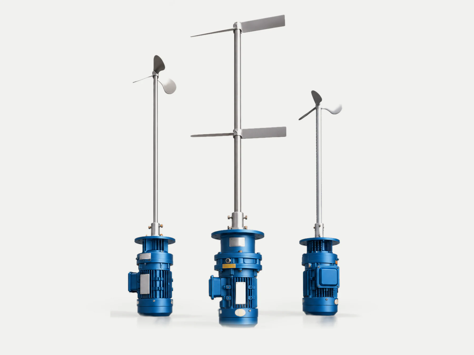
A clarifier scraper drive is not selected by asking how much power it needs. It is selected by asking how hard it fights at start-up. Four load traits make that the governing question: very low output speed, a near constant-torque demand, start-up resistance far above running resistance, and an overload risk that needs its own protection. Of the four, the last two decide the size — and only one of them shows up in a conventional power calculation. A drive that looks generous on power can still be undersized at the moment that matters: the first turn of the arm after a stop.
The reason is physical. After a shutdown the sludge settles and compacts, static friction rises, and the torque needed to break the scraper arm free sits well above the torque needed to keep it moving. A basin that has been stopped for a day does not come back as the machine you were running. So the order of work is fixed:
Compute the scraping resistance torque → multiply by the start-up factor to get the start-up torque → then set speed and power → check radial and axial shaft loads separately → finally fix ingress protection and overload protection.
The formulas in this article estimate order of magnitude only. The real scraping resistance has to be confirmed from basin and scraper-arm design data; no single empirical formula substitutes for a process judgement.
The Four Load Characteristics
| Trait | What it looks like on site | What it means for selection |
| Very low output speed | The larger the basin diameter, the slower the scraper arm turns | High reduction ratio; verify lubrication and heat rejection at low speed |
| Near constant torque | Resistance comes from sludge shear and blade friction, barely from speed | Select on torque, not on whether the power figure looks sufficient |
| Start-up resistance far above running resistance | Sludge settles and compacts during shutdown; static friction rises | Select on start-up torque, not on run torque |
| Overload risk | Sludge surges, foreign objects, ice at low temperature | Torque limitation or mechanical protection is mandatory |
The second row is the one that gets skipped. Constant torque means that halving the speed halves the power — but it does not reduce the torque demand at all. Torque is the quantity the drive train has to carry; power is only what falls out of torque at a given speed. A unit chosen because "the power looks sufficient" will be short of torque exactly where a scraper spends its life: at low speed, under a settled blanket.
Why Start-Up, Not Running, Is the Governing Case
The resistance while running and the resistance at start-up are not the same quantity:
| State | Where the resistance comes from | Relative size |
| Steady running | Sludge shear + blade friction | Baseline |
| Start-up after shutdown | The same, plus settled and compacted sludge, plus static friction | Markedly higher |
The longer the shutdown and the thicker the blanket, the wider that gap. And clarifier scrapers are usually intermittent machines — many basins are scraped on a set cycle, so stopping is the normal state rather than the exception.
That is why selecting on run torque comes out undersized. The unit will run happily and still sit at the edge of overload at every start. Something in the drive train then gives way first — a shear pin, a torque limiter, a bearing, a tooth flank — and it gives way while the machine is doing exactly what it was selected to do.
The Three Formulas, in Order
Step 1 — scraping resistance torque.
T_scrape = F_scrape · r_effF_scrape is the total scraping resistance, r_eff is the effective radius of action, and T_scrape is the resistance torque.
Step 2 — start-up torque, and the conversion from speed to angular velocity.
T_start = K_s · T_runT_run is the steady running torque, K_s is the start-up factor, and T_start is the torque required at start-up. The same step needs the output speed expressed as angular velocity:
ω = 2π · n / 60n is the output speed in r/min and ω is the angular velocity in rad/s.
Step 3 — required power.
P_req = T_start · ωP_req is the power required on the start-up case.
The order of these three is part of the method, not a matter of taste. Torque first, start-up factor second, power last. Run it backwards — take a power figure and work back to a torque — and the start-up amplification drops out of the calculation entirely. That is the most common arithmetic error in clarifier scraper selection, and it does not produce a marginal result; it produces one that is wrong by the factor that was skipped.
Two notes on the formulas themselves: they estimate order of magnitude only, and they say nothing about shaft load, which is a separate limit handled further down.
What Actually Sets the Start-Up Factor
K_s has no universal value. It is fixed by five things:
| Driver | Direction of effect |
| Basin type and diameter | The larger the basin and the longer the radius, the more uneven settlement and resistance become |
| Sludge thickness and nature | Thicker and more cohesive sludge raises start-up resistance |
| Shutdown duration | The longer the stop, the more pronounced the compaction and static friction |
| Risk of icing | Ice at low temperature adds resistance |
| Inlet water quality variation and flocculant dosing | Affects the settling state and the adhesion, and through them the start-up resistance |
All five are process conditions, not gearbox parameters. K_s is therefore confirmed by the process and equipment designers, and this article gives no value for it.
Which gives the sharpest boundary in the whole subject: a gearbox supplier can tell you what torque a unit will withstand. It cannot tell you how much torque your basin needs at start-up. Only the basin and scraper-arm design data answer the second question, and no catalogue carries it.
Shaft Load: Two Arrangements, Two Different Checks
Torque is one limit. The load carried by the output shaft is a second, independent limit, and it is checked on its own.
| Arrangement | Dominant load | What to verify |
| Suspended centre drive | Scraper arm weight plus sludge side pressure → bending moment | Effect of the bending moment on the bearing and the shaft |
| Bridge-mounted drive | Mainly axial and radial loads | Axial and radial components checked separately |
Why torque alone is not enough: the same unit can pass on torque and still fail early because the shaft load is over its limit — and it fails in a different way. Bearing spalling and tooth flank damage are not the same failure and they do not send you to the same place. Radial and axial loads have to be submitted and checked separately, as the selection rules require; "torque is fine, so it should be fine" is not a verification.
Ingress Protection, Sealing and the Maintenance Boundary
Site conditions on a clarifier are harsher than on most industrial drives:
| Item | Site condition | Requirement |
| Humidity and corrosion | Permanently damp; corrosive atmospheres such as hydrogen sulphide may be present | Corrosion protection and IP rating set by the site |
| Sealing | Water vapour, condensation, possible short-term immersion | Seal type matched to the duty |
| Maintenance access | Narrow working window inside the basin; high cost of stopping | Serviceability considered at the selection stage |
Maintenance access is the item most often postponed to "we will deal with it later". Its cost only appears in service: one intervention inside the basin can cost more in lost treatment time than the extra paid for a drive that is easier to service. Selection is the only point at which that trade can be made cheaply.
Overload Protection
Sludge surges, foreign objects and ice at low temperature all produce transient overload. Overload protection is not an option, and there are three families of it:
- Torque limiter (slip type or shear-pin type) — releases or shears above the set torque and protects the drive train;
- Electrical protection (overcurrent, overload relay) — slower to respond, but wider in coverage.
- Mechanical overrunning clutch — slips and releases above the set torque, acts repeatedly, and suits cases where the protection has to trip often.
The two are normally used together: mechanical protection absorbs the transient impact, electrical protection covers sustained overload. The type and setting of the protection are fixed by the machine and the process, and no value is given here.
Condition Table
| Site situation | Likely cause | Data still needed | Suggested action |
| Runs normally but struggles at every start | Selected on run torque | Shutdown duration, blanket thickness | Recalculate on the start-up case |
| Will not pull at low speed | Selected on power; torque is short | Actual torque demand across the speed range | Recalculate on the constant-torque characteristic |
| Torque adequate but bearings fail first | Shaft load never checked separately | Radial and axial loads | Check bearing loads separately |
| Frequent overload after the sludge volume rose | Changed duty not accounted for | Sludge range, peak condition | Review the start-up factor and the protection arrangement |
| Overload during the winter icing period | Ice adding resistance | Minimum temperature, likelihood of icing | Select for the most adverse case, or add protection |
| Bearings fail early in a corrosive atmosphere | Ingress protection or sealing inadequate | Corrosive atmosphere on site | Raise the IP rating or change the seal type |
| Vibration on a suspended centre drive | Excessive bending moment or installation deviation | Scraper arm weight, as-installed measurements | Check the bending moment and re-verify the installation |
| Basin out of service too long for maintenance | Poor maintenance access | Dismantling method, working window | Build serviceability into the next selection |
Field Checklist
Process data:
- Confirm the basin type (circular or rectangular) and the basin diameter.
- Confirm the scraper arm and blade form and the number of blades.
- Confirm the blanket thickness range and the sludge character.
- Confirm the scraping cycle and the duration of a single shutdown.
- Confirm the minimum ambient temperature and the likelihood of icing.
Selection calculation:
- Confirm the scraping resistance
F_scrapeand the effective radiusr_efffrom basin and scraper-arm data. - Compute the resistance torque
T_scrape. - Confirm the start-up factor
K_swith the process side and computeT_start. - Convert the target output speed to angular velocity
ωand computeP_req. - Submit and check the radial and axial loads separately.
Configuration and installation:
- Confirm that the IP rating and the corrosion protection suit the site atmosphere.
- Confirm the overload protection type (mechanical, electrical, or both).
- Confirm maintenance access (dismantling method, service window).
Common Mistakes and Where This Article Stops
Common mistakes:
- Selecting on run torque without the start-up factor. The unit runs, but every start sits at the edge of overload.
- Selecting on "the power looks sufficient". On a constant-torque load that leaves the drive short of torque at low speed.
- Reversing the order of the formulas. Working back from power to torque drops the start-up amplification out of the calculation.
- Replacing process confirmation with a single empirical formula. Basin and scraper-arm data are the basis, not a rule of thumb.
- Checking torque only. Radial and axial loads are independent limits.
- Treating overload protection as optional. Sludge volume, foreign objects and ice all produce transient overload.
- Ignoring maintenance access. The working window inside a basin is narrow and the cost of stopping is high; it belongs in selection.
Where this article stops:
- The four load traits, the three formulas, the basis for the start-up factor and the shaft-load distinction apply to selection preparation for clarifier scraper drives, including travelling-bridge and bridge-mounted arrangements.
- This article gives no values for torque, power, the start-up factor `K_s`, shaft load or protection settings.
- The formulas estimate order of magnitude only. The actual scraping resistance must be confirmed from basin and scraper-arm design data, and no single empirical formula replaces a process judgement.
- This article cites no customer cases and claims no operating results or retrofit gains, because no measured data is available for publication.
- It does not quantify where failures "mostly" come from; it gives the load traits and the selection inputs.
- A specific selection has to be confirmed jointly by the equipment designer and the process side; this article does not replace project-level strength and safety verification.
Selection Inputs
| No. | Input | Why it matters |
| 1 | Basin type and diameter | Sets the effective radius and the speed |
| 2 | Scraper arm and blade form and number | Sets how the resistance is distributed |
| 3 | Blanket thickness range and sludge character | Sets the resistance level and the start-up amplification |
| 4 | Scraping cycle and duration of one shutdown | Sets the start-up factor |
| 5 | Minimum ambient temperature and icing risk | Additional resistance |
| 6 | Total scraping resistance and effective radius | Used to compute T_scrape |
| 7 | Target output speed | Used to compute ω |
| 8 | Basis for the start-up factor | Confirmed by the process side |
| 9 | Radial and axial loads | Must be checked separately |
| 10 | IP rating and corrosion protection requirement | Follows the site atmosphere |
| 11 | Overload protection type required | Mechanical, electrical, or both |
| 12 | Maintenance window and dismantling method | Affects whole-life cost |
Items 6 and 8 are the core of this article: they decide whether the torque you calculate is the right torque. Without them, everything downstream is only a calculation that "looks about right".
About This Article and the Publisher
This article was written by the Chengfa Reducer (Changzhou) Co., Ltd. (CHINFAR) technical team and released after technical review. CHINFAR products are built and delivered on the joint manufacturing system shared with HUIGUANG.
Related pages:
- Water and wastewater treatment drives
- Agitator drives
- Industrial gearboxes
- Contact the CHINFAR technical team
The water and wastewater industry page covers which drive tasks and risks exist in a treatment plant and which product types are recommended. This article covers how one clarifier scraper drive is actually selected. One is the scenario and the risks; the other is the method.
Next Step
Send the twelve inputs above to sales@chinfar.com. Item 6 (total scraping resistance) and item 8 (the basis for the start-up factor) carry the most weight — without them, any model recommendation is a guess dressed up as a power calculation.
To be explicit: this article gives no torque, power, start-up factor or shaft-load values and no protection settings. The formulas estimate order of magnitude only and must be confirmed against basin and scraper-arm design data, and radial and axial shaft loads still require a separate check.